NCP4200MNR2G ON Semiconductor, NCP4200MNR2G Datasheet - Page 28
NCP4200MNR2G
Manufacturer Part Number
NCP4200MNR2G
Description
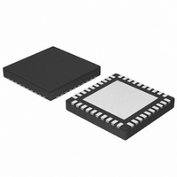
IC CONV SYNC BUCK PMBUS 40QFN
Manufacturer
ON Semiconductor
Datasheet
1.NCP4200MNR2G.pdf
(32 pages)
Specifications of NCP4200MNR2G
Applications
Converter, Intel VR11, VR11.1
Voltage - Input
1.7 ~ 24 V
Number Of Outputs
1
Voltage - Output
0.375 ~ 1.8 V
Operating Temperature
0°C ~ 85°C
Mounting Type
Surface Mount
Package / Case
40-VFQFN Exposed Pad
Output Voltage
0.375 V to 1.6 V
Output Current
500 uA
Input Voltage
1.7 V to 24 V
Switching Frequency
0.25 MHz to 6 MHz
Operating Temperature Range
0 C to + 85 C
Mounting Style
SMD/SMT
Duty Cycle (max)
100 %
Isolated/non-isolated
Non Isolated
Lead Free Status / RoHS Status
Lead free / RoHS Compliant
Available stocks
Company
Part Number
Manufacturer
Quantity
Price
Company:

Part Number:
NCP4200MNR2G
Manufacturer:
PHILIPS
Quantity:
124


Table 12. Manufacturer Specific Command Codes for the NCP4200
Code
Code
0xDO
0x8B
0x8C
0x8D
0x9A
0x9B
Cmd
0x80
0x88
0x96
0x99
Cmd
0xD1
R/W
R/W
R/W
R/W
R
R
R
R
R
R
R
R
R
Default
Default
0x4101
0x0002
0x0301
0x00
0x00
0x00
0x00
0x00
0x00
0x00
0x07
STATUS_ALERT
READ_VOUT
READ_IOUT
READ_POUT
MFR_ID
MFR_MODEL
MFR_REVISION
Lock/Reset
Mfr Config
Description
Description
http://onsemi.com
Bytes
Bytes
#
1
2
2
2
2
2
1
2
1
#
1
1
0x4101
0x0002
0x0301
28
Bit
Read−back output voltage. Voltage is read back in VID Mode.
Read−back output current. Current is read back in Linear Mode
(Amps).
Read−back Output Power, read back in Linear Mode in W’s.
7:6
Bit
Bit
7
6
5
4
3
2
1
0
1
0
5
4
3
2
1
0
BUS_TO_EN
ALERT_EN
FAULT_EN
MONITOR
ENABLE_
WARN
FAULT
Name
V
V
Res
Res
Res
Res
Res
Res
Name
Name
Reset
MON
MON
Lock
Res
Res
PSI
Gets asserted when V
programmed WARN limits.
Gets asserted when V
programmed FAULT limits.
Resets all registers to their POR Value. Has
no effect if Lock bit is set.
Logic 1 locks all limit values to their current
settings. Once this bit is set, all lockable
registers become read−only and cannot be
modified until the NCP4200 is powered down
and powered up again. This prevents rogue
programs such as viruses from modifying
critical system limit settings. (Lockable).
These bits sets the number of phases turned
on during PSI.
00 = CL set for 1 Phase (default)
01 = CL set for 2 Phases
10 = CL set for 1 Phase
11 = CL set for 1 Phase
Bus Timeout Enable. When the BUS_TO_EN
bit is set to 1, the I
enabled. In this state if, at any point during an
I
activity ceases for more than 35 ms, the
NCP4200 assumes the bus is locked and
releases the bus. This allows the NCP4200 to
be used with I
handle I
Enable the FAULT pin, Default = 1.
Enable the ALERT pin.
When the ENABLE_MONITOR bit is set to 1,
the NCP4200 starts conversions with the ADC
and monitors the voltages.
2
C transaction involving the NCP4200,
Comment
Comment
2
C timeouts. (Lockable).
2
C controllers that cannot
Description
Description
Description
2
C Timeout feature is
MON
MON
exceeds it
exceeds it
Related parts for NCP4200MNR2G
Image
Part Number
Description
Manufacturer
Datasheet
Request
R

Part Number:
Description:
Programmable Multi-phase Synchronous Buck Converter With Pmbus
Manufacturer:
ON Semiconductor
Datasheet:
Part Number:
Description:
ON Semiconductor [VOLTAGE REGULATOR]
Manufacturer:
ON Semiconductor
Datasheet:
Part Number:
Description:
357-036-542-201 CARDEDGE 36POS DL .156 BLK LOPRO
Manufacturer:
ON Semiconductor
Datasheet:
Part Number:
Description:
357-036-542-201 CARDEDGE 36POS DL .156 BLK LOPRO
Manufacturer:
ON Semiconductor
Datasheet:
Part Number:
Description:
357-036-542-201 CARDEDGE 36POS DL .156 BLK LOPRO
Manufacturer:
ON Semiconductor
Datasheet:
Part Number:
Description:
357-036-542-201 CARDEDGE 36POS DL .156 BLK LOPRO
Manufacturer:
ON Semiconductor
Datasheet:
Part Number:
Description:
357-036-542-201 CARDEDGE 36POS DL .156 BLK LOPRO
Manufacturer:
ON Semiconductor
Datasheet:
Part Number:
Description:
357-036-542-201 CARDEDGE 36POS DL .156 BLK LOPRO
Manufacturer:
ON Semiconductor
Datasheet:
Part Number:
Description:
357-036-542-201 CARDEDGE 36POS DL .156 BLK LOPRO
Manufacturer:
ON Semiconductor
Datasheet:
Part Number:
Description:
357-036-542-201 CARDEDGE 36POS DL .156 BLK LOPRO
Manufacturer:
ON Semiconductor
Datasheet:
Part Number:
Description:
357-036-542-201 CARDEDGE 36POS DL .156 BLK LOPRO
Manufacturer:
ON Semiconductor
Datasheet:
Part Number:
Description:
357-036-542-201 CARDEDGE 36POS DL .156 BLK LOPRO
Manufacturer:
ON Semiconductor
Datasheet:
Part Number:
Description:
Manufacturer:
ON Semiconductor
Datasheet:
Part Number:
Description:
Manufacturer:
ON Semiconductor
Datasheet: