NCP4200MNR2G ON Semiconductor, NCP4200MNR2G Datasheet - Page 25
NCP4200MNR2G
Manufacturer Part Number
NCP4200MNR2G
Description
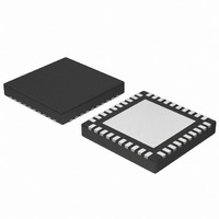
IC CONV SYNC BUCK PMBUS 40QFN
Manufacturer
ON Semiconductor
Datasheet
1.NCP4200MNR2G.pdf
(32 pages)
Specifications of NCP4200MNR2G
Applications
Converter, Intel VR11, VR11.1
Voltage - Input
1.7 ~ 24 V
Number Of Outputs
1
Voltage - Output
0.375 ~ 1.8 V
Operating Temperature
0°C ~ 85°C
Mounting Type
Surface Mount
Package / Case
40-VFQFN Exposed Pad
Output Voltage
0.375 V to 1.6 V
Output Current
500 uA
Input Voltage
1.7 V to 24 V
Switching Frequency
0.25 MHz to 6 MHz
Operating Temperature Range
0 C to + 85 C
Mounting Style
SMD/SMT
Duty Cycle (max)
100 %
Isolated/non-isolated
Non Isolated
Lead Free Status / RoHS Status
Lead free / RoHS Compliant
Available stocks
Company
Part Number
Manufacturer
Quantity
Price
Company:

Part Number:
NCP4200MNR2G
Manufacturer:
PHILIPS
Quantity:
124


Table 11. I
Code
Cmd
0x01
0x02
0x03
0x10
0x19
0x20
0x21
0x25
R/W
R/W
R/W
R/W
R/W
R/W
W
2
R
R
C Commands for the NCP4200
Default
0x0020
0xB0
0x80
0x17
0x00
0x20
0x00
NA
Operation
ON_OFF_Config
Clear_Faults
Write Protect
Capability
VOUT_MODE
VOUT_COMMAND
VOUT_MARGIN_HIGH
Description
http://onsemi.com
Bytes
#
1
1
0
1
1
1
2
2
Configures how the controller is turned on and off.
The Write_Protect command is used to control writing to the I
device. There is also a lock bit in the Manufacture Specific Registers
that once set will disable writes to all commands until the power to the
NCP4200 is cycled.
This command allows the host to get some information on the I
device.
25
00xx xxxx – Immediate Off
01xx xxxx – Soft Off
1000 xxxx – On (slew rate set by soft−start) − Default
1001 10xx – Margin Low (Act on Fault)
1010 10xx – Margin High (Act on Fault)
Bit
7:5
Writing any value to this command code will clear all Status Bits
immediately. The SMBus ALERT is deasserted on this command. If
the fault is still present the fault bit shall immediately be asserted
again.
Bit
6:5
3:0
The NCP4200 supports VID mode for programming the output
voltage.
Sets the output voltage using VID.
Sets the output voltage when operation command is set to Margin
High. Programmed in VID Mode.
4
3
2
1
0
7
4
1000 0000
0100 0000
0010 0000
0000 0000
0001 0000
Data Byte
Default
Default
000
000
01
1
0
1
1
1
1
1
Reserved for Future Use
This bit is read only. Switching starts when
commanded by the Control Pin and the
Operation Command, as set in Bits 3:0.
0: Unit ignores OPERATION commands over
the I
1: Unit responds to OPERATION command,
powerup may also depend upon Control input,
as described in Bit 2
0: Unit ignores EN pin
1: Unit responds EN pin, powerup may also
depend upon the Operation Register, as
described for Bit 3
Control Pin polarity
0 = Active Low
1 = Active High
This bit is read only.
1: means that when the controller is disabled it
will either immediately turn off or soft off (as set
in the Operation Command)
Disables all writes except to the Write_Protect
Command
Disables all writes except to the Write_Protect
and Operation Commands
Disables all writes except to the Write_Protect,
Operation, ON_OFF_Config and
VOUT_COMMAND Commands
Enables writes to all commands
Disables all writes except to
WRITE_PROTECT, PAGE and all
MFR−SPECIFIC Commands
PEC (Packet Error Checking is supported)
Max supported bus speed is 400 kHz
NCP4200 has an SMBus ALERT pin and ARA
is supported
Reserved for future use
2
C interface
Comment
Comment
Comment
Comment
2
C
2
C
Related parts for NCP4200MNR2G
Image
Part Number
Description
Manufacturer
Datasheet
Request
R

Part Number:
Description:
Programmable Multi-phase Synchronous Buck Converter With Pmbus
Manufacturer:
ON Semiconductor
Datasheet:
Part Number:
Description:
ON Semiconductor [VOLTAGE REGULATOR]
Manufacturer:
ON Semiconductor
Datasheet:
Part Number:
Description:
357-036-542-201 CARDEDGE 36POS DL .156 BLK LOPRO
Manufacturer:
ON Semiconductor
Datasheet:
Part Number:
Description:
357-036-542-201 CARDEDGE 36POS DL .156 BLK LOPRO
Manufacturer:
ON Semiconductor
Datasheet:
Part Number:
Description:
357-036-542-201 CARDEDGE 36POS DL .156 BLK LOPRO
Manufacturer:
ON Semiconductor
Datasheet:
Part Number:
Description:
357-036-542-201 CARDEDGE 36POS DL .156 BLK LOPRO
Manufacturer:
ON Semiconductor
Datasheet:
Part Number:
Description:
357-036-542-201 CARDEDGE 36POS DL .156 BLK LOPRO
Manufacturer:
ON Semiconductor
Datasheet:
Part Number:
Description:
357-036-542-201 CARDEDGE 36POS DL .156 BLK LOPRO
Manufacturer:
ON Semiconductor
Datasheet:
Part Number:
Description:
357-036-542-201 CARDEDGE 36POS DL .156 BLK LOPRO
Manufacturer:
ON Semiconductor
Datasheet:
Part Number:
Description:
357-036-542-201 CARDEDGE 36POS DL .156 BLK LOPRO
Manufacturer:
ON Semiconductor
Datasheet:
Part Number:
Description:
357-036-542-201 CARDEDGE 36POS DL .156 BLK LOPRO
Manufacturer:
ON Semiconductor
Datasheet:
Part Number:
Description:
357-036-542-201 CARDEDGE 36POS DL .156 BLK LOPRO
Manufacturer:
ON Semiconductor
Datasheet:
Part Number:
Description:
Manufacturer:
ON Semiconductor
Datasheet:
Part Number:
Description:
Manufacturer:
ON Semiconductor
Datasheet: