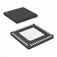
ISL6312ACRZ Intersil, ISL6312ACRZ Datasheet - Page 12

ISL6312ACRZ
Manufacturer Part Number
ISL6312ACRZ
Description
IC CTRLR PWM 4PHASE BUCK 48-QFN
Manufacturer
Intersil
Datasheet
1.ISL6312ACRZ.pdf
(35 pages)
Specifications of ISL6312ACRZ
Applications
Controller, Intel VR10, VR11, AMD CPU
Voltage - Input
5 ~ 12 V
Number Of Outputs
1
Voltage - Output
0.38 ~ 1.6 V
Operating Temperature
0°C ~ 70°C
Mounting Type
Surface Mount
Package / Case
48-VQFN
Lead Free Status / RoHS Status
Lead free / RoHS Compliant
Available stocks
Company
Part Number
Manufacturer
Quantity
Price
Company:
Part Number:
ISL6312ACRZ
Manufacturer:
INTERSIL
Quantity:
120
Company:
Part Number:
ISL6312ACRZ-T
Manufacturer:
ANAREN
Quantity:
44
Part Number:
ISL6312ACRZ-T
Manufacturer:
INTERSIL
Quantity:
20 000
current, and making the proper adjustment to each channel
pulse width based on the error. Intersil’s patented current-
balance method is illustrated in Figure 3, with error
correction for Channel 1 represented. In the figure, the cycle
average current, I
sample, I
The filtered error signal modifies the pulse width
commanded by V
I
correction is applied to each active channel.
Continuous Current Sampling
In order to realize proper current-balance, the currents in
each channel are sensed continuously every switching
cycle. During this time the current-sense amplifier uses the
ISEN inputs to reproduce a signal proportional to the
inductor current, I
scaled version of the inductor current.
The ISL6312A supports inductor DCR current sensing to
continuously sense each channel’s current for
ER
NOTE: Channel 3 and 4 are optional.
V
COMP
FIGURE 3. CHANNEL-1 PWM FUNCTION AND CURRENT-
toward zero. The same method for error signal
FILTER
FIGURE 4. CONTINUOUS CURRENT SAMPLING
1
, to create an error signal I
+
I
ER
BALANCE ADJUSTMENT
-
+
f(s)
I
1
COMP
L
AVG
-
. This sensed current, I
I
AVG
PWM
, is compared with the Channel 1
MODULATOR
WAVEFORM
to correct any unbalance and force
÷ N
SWITCHING PERIOD
RAMP
12
TIME
I
I
SEN
L
ER
Σ
+
-
.
PWM1
SEN
I
, is simply a
I
I
4
3
2
CONTROL
TO GATE
LOGIC
ISL6312A
ISL6312A
channel-current balance. The internal circuitry, shown in
Figure 5 represents Channel N of an N-channel converter.
This circuitry is repeated for each channel in the converter,
but may not be active depending on how many channels are
operating.
Inductor windings have a characteristic distributed
resistance or DCR (Direct Current Resistance). For
simplicity, the inductor DCR is considered as a separate
lumped quantity, as shown in Figure 5. The channel current
I
Equation 3 shows the s-domain equivalent voltage, V
across the inductor.
A simple R-C network across the inductor (R
extracts the DCR voltage, as shown in Figure 5. The voltage
across the sense capacitor, V
proportional to the channel current I
In some cases it may be necessary to use a resistor divider
R-C network to sense the current through the inductor. This
can be accomplished by placing a second resistor, R
across the sense capacitor. In these cases the voltage
across the sense capacitor, V
channel current I
L
V
V
, flowing through the inductor, passes through the DCR.
L
MOSFET
C
DRIVER
FIGURE 5. INDUCTOR DCR CURRENT SENSING
s ( )
s ( )
ISL6312A INTERNAL CIRCUIT
SAMPLE
=
=
I
------------------------------------- - DCR I
(
I
L
n
s R
⎛
⎝
⋅
⋅
-------------
DCR
(
s L
s L
CONFIGURATION
⋅
1
⋅
UGATE(n)
LGATE(n)
I
SEN
⋅
C
L
+
+
, and the resistor divider ratio, K.
DCR
1
+
⎞
⎠
+
1
-
)
⋅
)
V
R
V
IN
ISEN
C
⋅
C
C
(s)
L
, becomes proportional to the
, can be shown to be
-
INDUCTOR
R
L
1
L
V
, shown in Equation 4.
ISEN-(n)
ISEN+(n)
L
I
(s)
L
V
C
DCR
R
*R
-
(s)
C
2*
1
2
1
-
is OPTIONAL
and C)
February 1, 2011
C
V
OUT
OUT
2
L
FN9290.5
(EQ. 3)
(EQ. 4)
,
,


