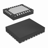
ISL8101IRZ Intersil, ISL8101IRZ Datasheet - Page 11

ISL8101IRZ
Manufacturer Part Number
ISL8101IRZ
Description
IC PWM CTRLR BUCK 2PHASE 24-QFN
Manufacturer
Intersil
Datasheet
1.ISL8101CRZ-T.pdf
(20 pages)
Specifications of ISL8101IRZ
Applications
Controller, Intel VRM9, VRM10, and AMD Hammer Applications
Voltage - Input
4.6 ~ 12 V
Number Of Outputs
1
Voltage - Output
0.6 ~ 2.3 V
Operating Temperature
-40°C ~ 85°C
Mounting Type
Surface Mount
Package / Case
24-VQFN Exposed Pad, 24-HVQFN, 24-SQFN, 24-DHVQFN
Lead Free Status / RoHS Status
Lead free / RoHS Compliant
VID4
TABLE 3. VRM10 VOLTAGE IDENTIFICATION CODES
0
1
1
1
1
1
1
1
1
1
1
1
1
1
1
1
1
1
1
1
1
1
1
1
1
1
1
1
1
1
1
0
0
0
0
0
0
0
0
0
0
0
VID3
0
1
1
1
1
1
1
1
1
1
1
1
1
1
1
0
0
0
0
0
0
0
0
0
0
0
0
0
0
0
0
1
1
1
1
1
1
1
1
1
1
1
(Continued)
VID2
0
1
1
1
1
1
1
0
0
0
0
0
0
0
0
1
1
1
1
1
1
1
1
0
0
0
0
0
0
0
0
1
1
1
1
1
1
1
1
0
0
0
VID1
0
1
1
0
0
0
0
1
1
1
1
0
0
0
0
1
1
1
1
0
0
0
0
1
1
1
1
0
0
0
0
1
1
1
1
0
0
0
0
1
1
1
11
VID0
0
0
0
1
1
0
0
1
1
0
0
1
1
0
0
1
1
0
0
1
1
0
0
1
1
0
0
1
1
0
0
1
1
0
0
1
1
0
0
1
1
0
VID5
0
1
0
1
0
1
0
1
0
1
0
1
0
1
0
1
0
1
0
1
0
1
0
1
0
1
0
1
0
1
0
1
0
1
0
1
0
1
0
1
0
1
1.0875
1.1000
1.1250
1.1375
1.1500
1.1625
1.1750
1.1875
1.2000
1.2125
1.2250
1.2375
1.2500
1.2625
1.2750
1.2875
1.3125
1.3250
1.3375
1.3500
1.3625
1.3750
1.3875
1.4000
1.4125
1.4250
1.4375
1.4500
1.4625
1.4750
1.4875
1.5000
1.5125
1.5250
1.5375
1.5500
1.5625
1.5750
1.5875
1.6000
1.1125
VDAC
1.300
ISL8101
ISL8101
DYNAMIC VID (VID-ON-THE-FLY)
The ISL8101 is capable of executing on-the-fly output
voltage changes. The way the ISL8101 reacts to a change in
the VID code is dependent on the VID configuration. In
VRM9 or AMD Hammer settings, the ISL8101 checks for a
change in the VID code four times each switching cycle. The
VID code is the bit pattern present at pins VID4-VID0. If a
new code is established and it stays the same for 12
switching cycles, the ISL8101 begins changing the reference
by making one step change every four switching cycles until
it reaches the new VID code. Figure 5 depicts such a
transition, from 1.5V to 1.7V
In VRM10 setting, the ISL8101 checks for a change in the VID
code six times each switching cycle. If a new code is
established and it stays the same for 3 consecutive readings,
the ISL8101 recognizes the change and increments the
reference. Specific to VRM10, the processor controls the VID
transitions and is responsible for incrementing or
decrementing one VID step at a time. In VRM10 setting, the
ISL8101 will immediately change the reference to the new
requested value as soon as the request is validated; in cases
where the reference step is too large, the sudden change can
trigger overcurrent or overvoltage events.
In non-VRM10 settings, due to the way the ISL8101
recognizes VID code changes, up to one full switching
period may pass before a VID change registers. Thus, the
total time required for a VID change, t
the switching frequency (f
and the time required to register the VID change. The
approximate time required for a ISL8101-based converter in
VRM9 configuration running at typical f
perform a 1.5V-to-1.7V reference voltage change is about
196µs, as calculated using Equation 6. (this example is also
illustrated in Figure 5).
1.5V
1.5V
t
DVID
01110
FIGURE 5. TYPICAL DYNAMIC-VID OPERATION, VRM9 DAC
≅
V
V
REF
OUT
---- -
f
1
S
⎛
⎜
⎝
00110
4 V
-------------------- -
(100mV/DIV)
(100mV/DIV)
0.025
Δ
SETTING
VID
VID CHANGE OCCURS HERE
+
13
⎞
⎟
⎠
S
), the size of the change (ΔV
V
VID
DVID
S
(222kHz) to
, is dependent on
July 28, 2008
(EQ. 6)
FN9223.1
ID
),


