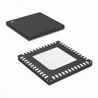
ISL9502CRZ Intersil, ISL9502CRZ Datasheet - Page 16

ISL9502CRZ
Manufacturer Part Number
ISL9502CRZ
Description
IC CTRLR PWM 2PHASE GPU 48-QFN
Manufacturer
Intersil
Datasheet
1.ISL9502CRZ-T.pdf
(24 pages)
Specifications of ISL9502CRZ
Pwm Type
Controller
Number Of Outputs
1
Frequency - Max
500kHz
Voltage - Supply
4.75 V ~ 5.25 V
Buck
Yes
Boost
No
Flyback
No
Inverting
No
Doubler
No
Divider
No
Cuk
No
Isolated
No
Operating Temperature
-10°C ~ 100°C
Package / Case
48-VQFN
Frequency-max
500kHz
Lead Free Status / RoHS Status
Lead free / RoHS Compliant
Duty Cycle
-
Refer to Figure 17, the second level of overvoltage
protection behaves differently. If the output exceeds 1.7V, an
OV fault is immediately declared, PGOOD is latched low and
the low-side FETs are turned on. The low-side FETs will
remain on until the output voltage is pulled down below
about 0.85V at which time all FETs are turned off. If the
output again rises above 1.7V, the protection process is
repeated. This offers the maximum amount of protection
against a shorted high-side FET while preventing output
ringing below ground. The 1.7V OV cannot be reset with
VR_ON, but rather requires that VDD power be recycled.
The 1.7V OV detector is active at all times that the controller
is enabled, including after one of the other faults occurs so
that the processor is protected against high-side FET
leakage while the FETs are commanded off.
The ISL9502 has a thermal throttling feature. If the voltage
on the NTC pin goes below the 1.18V over-temperature
threshold, the VRHOT# pin is pulled low indicating the need
for thermal throttling to the system oversight processor. No
other action is taken within the ISL9502 in response to NTC
pin voltage.
Component Selection and Application
Soft-Start and Mode Change Slew Rates
The ISL9502 uses 2 slew rates for various modes of
operation. The first is a slow slew rate, used to reduce inrush
current during start-up. It can also be used to reduce audible
noise when entering or exiting the different modes of
operation outlined in Table 2. The assertion of SET1 HIGH
produces a faster slew rate than when it is asserted LOW.
Faster slew rates to exit DCM mode enhances system
performance by achieving full synchronous regulation more
quickly. Note that the SOFT cap current is bidirectional. The
current is flowing into the SOFT capacitor when the output
voltage is commanded to rise, and out of the SOFT capacitor
when the output voltage is commanded to fall.
The two slew rates are determined by commanding one of
two current sources onto the SOFT pin. As can be seen in
Figure 22, the SOFT pin has a capacitance to ground. Also,
the SOFT pin is the input to the error amplifier and is,
therefore, the commanded system voltage. Depending on
the state of the system, one of the two currents shown in
Figure 22 will be used to charge or discharge this capacitor,
thereby controlling the slew rate of the commanded voltage.
These currents can be found under the SOFT-START
CURRENT section of the Electrical Specification Table.
16
ISL9502
The first current, labelled I
Table as 41µA. This current is used during soft-start. The
second current, I
two currents, labelled I
Table. This total current is typically 200µA with a minimum of
175µA.
Equation 1 dictates how to program the desired fast slew
rate of VSEL and mode transitions, where RATE represents
the desired dV/dt for the application.
Using a SLEWRATE of 10mV/µs, and the typical I
given in the Electrical Specification Table, C
A choice of 0.015µF would guarantee a RATE of 10mV/µs is
met for minimum I
Specification Table. With this C
dV/dt, from VR_ON assertion to VBOOT voltage (1.2V), is
given by the following equation:
Selecting RBIAS
To properly bias the ISL9502, a reference current is
established by placing a 147kΩ, 1% tolerance resistor from
the RBIAS pin to ground. This will provide a highly accurate,
10µA current source from which OCSET reference current
can be derived.
Care should be taken in layout that the resistor is placed
very close to the RBIAS pin and that a good quality signal
ground is connected to the opposite side of the RBIAS
resistor. Do not connect any other components to this pin as
this would negatively impact performance. Capacitance on
this pin would create instabilities and should be avoided.
C
C
dV
-------
dt
FIGURE 22. SOFT PIN CURRENT SOURCES FOR FAST AND
SOFT
SOFT
=
-------------------
C
SOFT
=
=
I
SS
200µA
---------------- -
RATE
I
ST
C
SOFT
SLOW SLEW RATES
=
---------------------- -
0.015µF
⁄
SS2
41µA
(
ST
10mV 1µs
+
SOFT
sums with I
value, given in the Electrical
ST
V
REF
I
⁄
SS1
=
in the Electrical Specification
SS1
2.8mV µs
)
, is given in the Specification
SOFT
SS1
⁄
I
SS2
ISL9502
selection, the slower
to get the larger of the
AMPLIFIER
+
ERROR
SOFT
is
ST
July 17, 2006
value
(EQ. 1)
(EQ. 2)
(EQ. 3)
FN9275.1


