AD652JP Analog Devices Inc, AD652JP Datasheet - Page 25
AD652JP
Manufacturer Part Number
AD652JP
Description
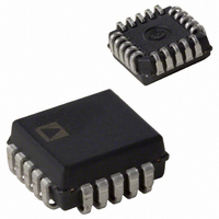
IC V-F CONV SYNCH MONO 5V 20PLCC
Manufacturer
Analog Devices Inc
Type
Voltage to Frequencyr
Datasheet
1.AD652JPZ.pdf
(28 pages)
Specifications of AD652JP
Rohs Status
RoHS non-compliant
Frequency - Max
2MHz
Full Scale
±25ppm/°C
Linearity
±0.005%
Mounting Type
Surface Mount
Package / Case
20-LCC (J-Lead)
Converter Function
VFC
Full Scale Frequency
2000
Power Supply Requirement
Single/Dual
Single Supply Voltage (max)
36V
Single Supply Voltage (min)
12V
Dual Supply Voltage (typ)
±15V
Dual Supply Voltage (min)
±6V
Dual Supply Voltage (max)
±18V
Operating Temperature (min)
0C
Operating Temperature (max)
70C
Operating Temperature Classification
Commercial
Package Type
PLCC
Lead Free Status / Rohs Status
Not Compliant
Available stocks
Company
Part Number
Manufacturer
Quantity
Price

Part Number:
AD652JP
Manufacturer:
ADI/亚德诺
Quantity:
20 000
Company:
Part Number:
AD652JP-REEL
Manufacturer:
Analog Devices Inc
Quantity:
10 000
Company:
Part Number:
AD652JP-REEL7
Manufacturer:
Analog Devices Inc
Quantity:
10 000
Part Number:
AD652JPZ
Manufacturer:
ADI/亚德诺
Quantity:
20 000


OUTLINE DIMENSIONS
0.048 (1.21)
0.042 (1.07)
(0.50)
0.200 (5.08)
0.125 (3.18)
0.020
0.200 (5.08)
R
0.048 (1.21)
0.042 (1.07)
0.358 (9.09)
0.342 (8.69)
0.023 (0.58)
0.014 (0.36)
MAX
CONTROLLING DIMENSIONS ARE IN INCHES; MILLIMETER DIMENSIONS
(IN PARENTHESES) ARE ROUNDED-OFF INCH EQUIVALENTS FOR
REFERENCE ONLY AND ARE NOT APPROPRIATE FOR USE IN DESIGN
4
8
0.395 (10.02)
CONTROLLING DIMENSIONS ARE IN INCHES; MILLIMETER DIMENSIONS
(IN PARENTHESES) ARE ROUNDED-OFF INCH EQUIVALENTS FOR
REFERENCE ONLY AND ARE NOT APPROPRIATE FOR USE IN DESIGN
0.385 (9.78)
CONTROLLING DIMENSIONS ARE IN INCHES; MILLIMETER DIMENSIONS
(IN PARENTHESES) ARE ROUNDED-OFF INCH EQUIVALENTS FOR
REFERENCE ONLY AND ARE NOT APPROPRIATE FOR USE IN DESIGN
0.356 (9.04)
0.350 (8.89) SQ
SQ
3
(PINS DOWN)
(0.13)
9
0.005
TOP VIEW
MIN
PIN 1
0.100 (2.54)
0.064 (1.63)
Figure 39. 16-Lead Ceramic Dual In-Line Package [CERDIP]
0.088 (2.24)
0.054 (1.37)
Figure 40. 20-Lead Plastic Leaded Chip Carrier [PLCC]
Figure 41. 20-Terminal Leadless Chip Carrier [LCC]
16
Dimensions shown in inches and (millimeters)
19
13
0.840 (21.34) MAX
COMPLIANT TO JEDEC STANDARDS MO-047AA
(9.09)
SQ
0.358
1
MAX
18
14
SQ
Dimensions shown in inches and (mm)
Dimensions shown in inches and (mm)
0.100
(2.54)
0.098 (2.49)
BSC
0.056 (1.42)
0.042 (1.07)
0.050
(1.27)
BSC
MAX
0.070 (1.78)
0.030 (0.76)
Rev. C | Page 25 of 28
0.075 (1.91)
0.011 (0.28)
0.007 (0.18)
0.095 (2.41)
0.075 (1.90)
9
0.055 (1.40)
0.045 (1.14)
0.075 (1.91)
0.180 (4.57)
0.165 (4.19)
8
0.120 (3.04)
0.090 (2.29)
(P-20A)
(E-20A)
(Q-16)
R TYP
REF
0.310 (7.87)
0.220 (5.59)
SEATING
PLANE
REF
0.060 (1.52)
0.015 (0.38)
0.150 (3.81)
MIN
0.021 (0.53)
0.013 (0.33)
0.032 (0.81)
0.026 (0.66)
0.20 (0.51)
MIN
0.025 (0.64) MIN
13
19
18
14
BOTTOM
20
VIEW
0.150 (3.81)
1
BSC
0.330 (8.38)
0.290 (7.37)
4
8
3
9
0.200 (5.08)
REF
0.100 (2.54) REF
15°
0°
45° TYP
0.015 (0.38)
MIN
0.050 (1.27)
BSC
0.020 (0.50)
0.028 (0.71)
0.022 (0.56)
R
0.320 (8.13)
0.290 (7.37)
0.015 (0.38)
0.008 (0.20)
BOTTOM
(PINS UP)
VIEW
AD652
Related parts for AD652JP
Image
Part Number
Description
Manufacturer
Datasheet
Request
R

Part Number:
Description:
±1.7g Dual-Axis IMEMS Accelerometer Evaluation Board
Manufacturer:
Analog Devices Inc
Datasheet:

Part Number:
Description:
Inertial Sensor Evaluation System
Manufacturer:
Analog Devices Inc
Datasheet:
Part Number:
Description:
Manufacturer:
Analog Devices Inc
Datasheet:
Part Number:
Description:
Manufacturer:
Analog Devices Inc
Datasheet:
Part Number:
Description:
Manufacturer:
Analog Devices Inc
Datasheet:
Part Number:
Description:
Manufacturer:
Analog Devices Inc
Datasheet:
Part Number:
Description:
Manufacturer:
Analog Devices Inc
Datasheet:
Part Number:
Description:
Manufacturer:
Analog Devices Inc
Datasheet:
Part Number:
Description:
Manufacturer:
Analog Devices Inc
Datasheet:
Part Number:
Description:
Manufacturer:
Analog Devices Inc
Datasheet:
Part Number:
Description:
Manufacturer:
Analog Devices Inc
Datasheet:
Part Number:
Description:
Manufacturer:
Analog Devices Inc
Datasheet:
Part Number:
Description:
Manufacturer:
Analog Devices Inc
Datasheet: