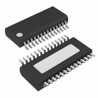
MAX8734AEEI+ Maxim Integrated Products, MAX8734AEEI+ Datasheet - Page 31

MAX8734AEEI+
Manufacturer Part Number
MAX8734AEEI+
Description
IC PWR SUPPLY CONTROLLER 28QSOP
Manufacturer
Maxim Integrated Products
Datasheet
1.MAX8734AEEIT.pdf
(33 pages)
Specifications of MAX8734AEEI+
Applications
Power Supply Controller
Voltage - Input
4.5 ~ 24 V
Current - Supply
25µA
Operating Temperature
-40°C ~ 85°C
Mounting Type
Surface Mount
Package / Case
28-QSOP
Product
Power Monitors
Operating Temperature Range
- 40 C to + 85 C
Mounting Style
SMD/SMT
Accuracy
1.5 %
Supply Current (max)
50 uA
Supply Voltage (max)
4.5 V
Supply Voltage (min)
24 V
Case
SSOP
Dc
06+
Lead Free Status / RoHS Status
Lead free / RoHS Compliant
Voltage - Supply
-
Lead Free Status / Rohs Status
Lead free / RoHS Compliant
• Make all pin-strap control input connections (SKIP,
1) Place the power components first with ground ter-
2) Mount the controller IC adjacent to the synchronous-
3) Group the gate-drive components (BST_ diode and
4) Make the DC-DC controller ground connections as
Table 5. MAX8732A/MAX8733A/MAX8734A and MAX1777/MAX1977/MAX1999 Differences
Line Transient Behavior
Ultrasonic Mode
LDO3 and LDO5 Sequencing
Soft-Shutdown Enable Delay
High-Output Impedance in UVLO
ILIM_, etc.) to GND or V
minals adjacent (N2/N4 source, C
anode). If possible, make all these connections on
the top layer with wide, copper-filled areas.
rectifier MOSFETs, preferably on the back side to
keep DH_, GND, and the DL_ gate drive lines short
and wide. The DL_ gate trace must be short and
wide, measuring 50 mils to 100 mils wide if the
MOSFET is 1in from the controller device.
capacitor, V+ bypass capacitor) together near the
controller device.
follows: near the device, create a small analog
ground plane. Connect the small analog ground
plane to GND (Figure 13) and use the plane for the
ground connection for the REF and V
capacitors, FB dividers, and ILIM resistors (if any).
Create another small ground island for PGND, and
use the plane for the V+ bypass capacitor, placed
Supply Controllers for Notebook Computers
High-Efficiency, Quad-Output, Main Power-
______________________________________________________________________________________
CC
of the device.
Improved line transient behavior requires only
a 0.1µF filter capacitor on V+. Allows fast
rising-edge line transients of 10V/µs and
falling-edge line transients of 5V/µs.
Simplified Z pattern offers better efficiency
and smoother transition into continuous-
conduction mode.
LDO3 starts only after LDO5 is in regulation,
reducing the inrush current when SHDN goes
high.
Soft-shutdown (10Ω discharge feature) is
enabled immediately when an output is
enabled, and is not dependent on the 22ms
(typ) startup undervoltage blanking timer.
When LDO5 falls below its 4V (typ) UVLO
threshold, DH_ and DL_ are immediately
pulled low, and the outputs are high
impedance. The outputs are discharged by
the load.
Layout Procedure
MAX8732A/MAX8733A/MAX8734A
IN_
, C
CC
OUT_
bypass
, D1
5) On the board’s top side (power planes), make a
6) Connect the output power planes (V
very close to the device. Connect the AGND and
PGND planes together at the GND pin of the device.
star ground to minimize crosstalk between the two
sides. The top-side star ground is a star connection
of the input capacitors and synchronous rectifiers.
Keep the resistance low between the star ground
and the source of the synchronous rectifiers for
accurate current limit. Connect the top-side star
ground (used for MOSFET, input, and output
capacitors) to the small island with a single short,
wide connection (preferably just a via).
Create PGND islands on the layer just below the
top-side layer (refer to the MAX1999 EV kit for an
example) to act as an EMI shield if multiple layers
are available (highly recommended). Connect each
of these individually to the star ground via, which
connects the top side to the PGND plane. Add one
more solid ground plane under the device to act as
an additional shield, and also connect the solid
ground plane to the star ground via.
ground planes) directly to the output filter capacitor
positive and negative terminals with multiple vias.
A 4Ω/4.7µF filter capacitor is required on V+ to
limit the dV/dt on the V+ pin.
Original “W” pattern conducts through the high-
side MOSFET’s body diode, reducing efficiency.
Transition between ultrasonic mode and
continuous-conduction mode is not as smooth.
LDO3 and LDO5 start up together at the current
limit of each LDO, causing large inrush currents
through the 4Ω series resistor at V+.
Soft-shutdown (10Ω discharge feature) is
enabled only after the 22ms (typ) startup
undervoltage blanking time. This causes DL_ to
be driven high if the part is commanded to turn
off before the 22ms timer.
When LDO5 falls below its 4V (typ) UVLO
threshold, DH_ is immediately pulled low and
DL_ forced high to clamp the output rails. This
causes the outputs to swing below ground.
MAX1777/MAX1977/MAX1999
CORE
and system
31


