LM2636M/NOPB National Semiconductor, LM2636M/NOPB Datasheet - Page 7
LM2636M/NOPB
Manufacturer Part Number
LM2636M/NOPB
Description
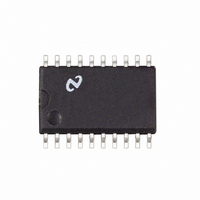
IC REG SYNCH BUCK 5-BIT 20-SOIC
Manufacturer
National Semiconductor
Datasheet
1.LM2636MNOPB.pdf
(15 pages)
Specifications of LM2636M/NOPB
Applications
Power Supplies
Current - Supply
2.5mA
Voltage - Supply
4.5 V ~ 5.5 V
Operating Temperature
0°C ~ 125°C
Mounting Type
Surface Mount
Package / Case
20-SOIC (7.5mm Width)
Lead Free Status / RoHS Status
Lead free / RoHS Compliant
Other names
*LM2636M
*LM2636M/NOPB
LM2636M
*LM2636M/NOPB
LM2636M


Test Circuit
Applications Information
OVERVIEW
The LM2636 is a high speed synchronous PWM buck regu-
lator controller designed for VRM vendors or motherboard
manufacturers who need to build on-board power supplies
for Cyrix MII, Pentium II or Deschutes microprocessors. It
has a built-in 5-bit DAC to decode the 5-bit word provided by
the CPU and supply the corresponding voltage. It also has
the power good (PWRGD) and output enable (OUTEN) func-
tions required by the VRM specification. It employs a voltage
mode control scheme plus two fast responding comparators
to quickly respond to large load transients. It has two fast
FET drivers to drive the high-side and low-side NMOS
switches of a synchronous buck regulator. The PWM fre-
quency is adjustable from 50 kHz to 1 MHz through an
external resistor. Over-voltage protection is achieved by
shutting off the high-side driver and turning on the low-side
driver 100% of the time. Current limiting is implemented by
sensing V
for the present switching cycle when an over current condi-
tion is detected. Soft start functionality is realized through an
internal digital counter and an internal DAC.
THEORY OF OPERATION
Start Up
When V
and the VID code is valid, the soft start circuitry starts to
work. The duration of the soft start is determined by an
internal digital counter and the switching frequency. During
soft start, the output of the error amplifier is allowed to
increase gradually. When the counter has counted 2,048
clock cycles, the soft start session ends and the output
voltage level of the error amplifier is released and allowed to
go to a value that is determined by the feedback loop.
PWRGD pin is forced low during soft start and is turned over
CC
DS
voltage exceeds 4.2V, OUTEN pin is a logic high
of the high-side NMOS switch and shutting it off
FIGURE 2.
7
to output voltage monitoring circuitry after that. Before V
reaches 4.2V, all internal logic is in a power on reset state
and the two FET drivers are disabled.
During normal operation, if V
the internal circuitry will go into power on reset again. The
hysteresis helps decrease the noise sensitivity on the V
pin. After soft starts ends and during normal operation, if the
converter output voltage exceeds 115% of the DAC output
voltage, the LM2636 will lock into over voltage protection
mode. The high side drive will be disabled, and the low side
drive will be high. There are two ways to clear the mode. One
is to cycle V
OUTEN level. After the over voltage protection mode is
cleared, the LM2636 will enter the soft start session and start
over.
Normal Operation
During the normal operation mode, the LM2636 regulates
the converter output voltage by adjusting the duty ratio. The
output voltage is determined by the 5-bit VID code set by the
user/load.
The PWM frequency is set by the external resistor between
FREQ_ADJ pin and ground. The resistance needed for a
desired switching frequency is:
For example, if the desired switching frequency is 300 kHz,
the resistance should be around 84 kΩ.
The minimum allowable PWM frequency is 5 kHz.
MOSFET Gate Drive
The LM2636 has two gate drives that are suitable for driving
external N-MOSFETs in a synchronous buck topology. The
power for the two FET drivers is supplied by the BOOTV pin.
This BOOTV voltage needs to be at least one V
than the converter input voltage for the high side FET to be
CC
voltage once. The other is to toggle the
CC
voltage drops below 3.8V,
10083404
GS(th)
www.national.com
higher
CC
CC
Related parts for LM2636M/NOPB
Image
Part Number
Description
Manufacturer
Datasheet
Request
R

Part Number:
Description:
5-Bit Programmable Synchronous Buck Regulator Controller
Manufacturer:
National Semiconductor
Datasheet:
Part Number:
Description:
National Semiconductor [8-Bit D/A Converter]
Manufacturer:
National Semiconductor
Datasheet:
Part Number:
Description:
National Semiconductor [Media Coprocessor]
Manufacturer:
National Semiconductor
Datasheet:
Part Number:
Description:
Digitally Controlled Tone and Volume Circuit with Stereo Audio Power Amplifier, Microphone Preamp Stage and National 3D Sound
Manufacturer:
National Semiconductor
Datasheet:
Part Number:
Description:
Digitally Controlled Tone and Volume Circuit with Stereo Audio Power Amplifier, Microphone Preamp Stage and National 3D Sound
Manufacturer:
National Semiconductor
Datasheet:
Part Number:
Description:
AC97 Rev 2 Codec with Sample Rate Conversion and National 3D Sound
Manufacturer:
National Semiconductor
Part Number:
Description:
Manufacturer:
National Semiconductor
Datasheet:
Part Number:
Description:
Manufacturer:
National Semiconductor
Datasheet:
Part Number:
Description:
General Purpose, Low Voltage, Low Power, Rail-to-Rail Output Operational Amplifiers
Manufacturer:
National Semiconductor
Datasheet:
Part Number:
Description:
8-bit 20 MSPS flash A/D converter.
Manufacturer:
National Semiconductor
Datasheet:
Part Number:
Description:
Low Noise Quad Operational Amplifier
Manufacturer:
National Semiconductor
Datasheet:
Part Number:
Description:
Quad Differential Line Receivers
Manufacturer:
National Semiconductor
Datasheet:
Part Number:
Description:
Quad High Speed Trapezoidal? Bus Transceiver
Manufacturer:
National Semiconductor
Datasheet:
Part Number:
Description:
Dual Line Receiver
Manufacturer:
National Semiconductor
Datasheet: