LM2636M/NOPB National Semiconductor, LM2636M/NOPB Datasheet - Page 5
LM2636M/NOPB
Manufacturer Part Number
LM2636M/NOPB
Description
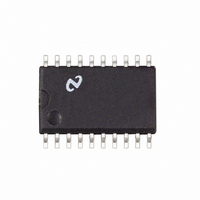
IC REG SYNCH BUCK 5-BIT 20-SOIC
Manufacturer
National Semiconductor
Datasheet
1.LM2636MNOPB.pdf
(15 pages)
Specifications of LM2636M/NOPB
Applications
Power Supplies
Current - Supply
2.5mA
Voltage - Supply
4.5 V ~ 5.5 V
Operating Temperature
0°C ~ 125°C
Mounting Type
Surface Mount
Package / Case
20-SOIC (7.5mm Width)
Lead Free Status / RoHS Status
Lead free / RoHS Compliant
Other names
*LM2636M
*LM2636M/NOPB
LM2636M
*LM2636M/NOPB
LM2636M


V
V
V
V
V
V
∆V
∆V
V
V
V
V
V
t
t
I
V
V
I
t
PWRGD
PWRBAD
OUTEN
VID
SS
Electrical Characteristics
OUTEN_IH
OUTEN_IL
REF
REF_LOAD
REF_525
REF_475
SAWL
SAWH
PWRBAD_GD
PWRGD_BAD
OVP
VID_IH
VID_IL
V
T
Note 1: Absolute Maximum Ratings are limits beyond which damage to the device may occur. Recommended Operating Conditions are conditions under which
the device operates correctly. Recommended Operating Conditions do not imply guaranteed performance limits.
Note 2: Maximum allowable DC power dissipation is a function of the maximum junction temperature, T
the ambient temperature, T
Symbol
REF_LOAD
REF_LINE
J
CC
= +25˚C. Limits appearing in boldface type apply over 0˚C to +70˚C.
= 5V unless otherwise indicated under the Conditions column. Typicals and limits appearing in plain type apply for T
OUTEN Pin Input Logic
Low to Logic High Trip
Point
OUTEN Pin Input Logic
High to Logic Low Trip
Point
Band Gap Reference
Reference Voltage at
Full Load
Reference Voltage at
High Line
Reference Voltage at
Low Line
Reference Voltage Load
Regulation
Reference Voltage Line
Regulation
Ramp Signal Valley
Voltage
Ramp Signal Peak
Voltage
PWRGD Pin ↓ Trip
Points (see Pin
Description for Pin 13)
PWRGD Pin
Points (see Pin
Description for Pin 13)
Over-voltage Protection
Trip Point
Power Good Response
Time
Power Not Good
Response Time
OUTEN Pin Internal
Pull-Up Current
VID Pins Logic High Trip
Point
VID Pins Logic Low Trip
Point
VID0:4 Internal Pull-Up
Current
Soft Start Duration
Parameter
A
. The maximum allowable power dissipation at any ambient temperature is calculated using:
↑
Trip
OUTEN Voltage
OUTEN Voltage ↓
I
I
I
I
I
I
5.25V to 4.75V
% above DAC Output Voltage, when
Output Voltage
% below DAC Output Voltage, when
Output Voltage ↓
% above DAC Output Voltage, when
Output Voltage ↓
% below DAC Output Voltage, when
Output Voltage
% above DAC Output Voltage
V
V
VREF
VREF
VREF
VREF
VREF
VREF
SENSE
SENSE
(Continued)
= 0 mA
= 0.5 mA, Sourcing
= 0 mA, V
= 0 mA, V
= 0.5 mA, Sourcing
= 0 mA, V
Rises from 0V to Rated V
Falls from Rated V
Conditions
↑
↑
CC
CC
CC
↑
= 5.25V
= 4.75V
Changes from
5
OUT
to 0V
OUT
JMAX
1.225
1.223
1.226
1.224
, the junction-to-ambient thermal resistance, θ
Min
3.5
3.5
60
60
2
2
1.256
1.254
1.257
1.255
2048
−0.5
1.25
3.25
Typ
−10
3.0
1.8
3.0
1.8
−2
−8
10
15
90
90
8
6
6
1.287
1.285
1.288
1.286
Max
130
130
1.5
1.3
15
15
www.national.com
cycles
JA
Units
clock
A
mV
mV
, and
µA
µA
µs
µs
%
%
%
V
V
V
V
V
V
V
V
V
V
=
Related parts for LM2636M/NOPB
Image
Part Number
Description
Manufacturer
Datasheet
Request
R

Part Number:
Description:
5-Bit Programmable Synchronous Buck Regulator Controller
Manufacturer:
National Semiconductor
Datasheet:
Part Number:
Description:
National Semiconductor [8-Bit D/A Converter]
Manufacturer:
National Semiconductor
Datasheet:
Part Number:
Description:
National Semiconductor [Media Coprocessor]
Manufacturer:
National Semiconductor
Datasheet:
Part Number:
Description:
Digitally Controlled Tone and Volume Circuit with Stereo Audio Power Amplifier, Microphone Preamp Stage and National 3D Sound
Manufacturer:
National Semiconductor
Datasheet:
Part Number:
Description:
Digitally Controlled Tone and Volume Circuit with Stereo Audio Power Amplifier, Microphone Preamp Stage and National 3D Sound
Manufacturer:
National Semiconductor
Datasheet:
Part Number:
Description:
AC97 Rev 2 Codec with Sample Rate Conversion and National 3D Sound
Manufacturer:
National Semiconductor
Part Number:
Description:
Manufacturer:
National Semiconductor
Datasheet:
Part Number:
Description:
Manufacturer:
National Semiconductor
Datasheet:
Part Number:
Description:
General Purpose, Low Voltage, Low Power, Rail-to-Rail Output Operational Amplifiers
Manufacturer:
National Semiconductor
Datasheet:
Part Number:
Description:
8-bit 20 MSPS flash A/D converter.
Manufacturer:
National Semiconductor
Datasheet:
Part Number:
Description:
Low Noise Quad Operational Amplifier
Manufacturer:
National Semiconductor
Datasheet:
Part Number:
Description:
Quad Differential Line Receivers
Manufacturer:
National Semiconductor
Datasheet:
Part Number:
Description:
Quad High Speed Trapezoidal? Bus Transceiver
Manufacturer:
National Semiconductor
Datasheet:
Part Number:
Description:
Dual Line Receiver
Manufacturer:
National Semiconductor
Datasheet: