L9953 STMicroelectronics, L9953 Datasheet - Page 28
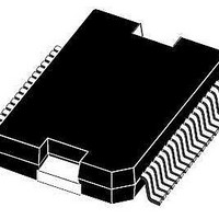
L9953
Manufacturer Part Number
L9953
Description
IC DVR DOOR ACTUATOR POWERSO-36
Manufacturer
STMicroelectronics
Datasheet
1.L9953XPTR.pdf
(38 pages)
Specifications of L9953
Applications
Door Actuator
Current - Supply
7mA
Voltage - Supply
7 V ~ 28 V
Operating Temperature
-40°C ~ 150°C
Mounting Type
Surface Mount
Package / Case
PowerSO-36 Exposed Bottom Pad
Mounting Style
SMD/SMT
Lead Free Status / RoHS Status
Lead free / RoHS Compliant
Available stocks
Company
Part Number
Manufacturer
Quantity
Price

Part Number:
L9953EXP
Manufacturer:
ST
Quantity:
20 000
Part Number:
L9953LXP
Manufacturer:
ST
Quantity:
20 000
Part Number:
L9953LXPTR
Manufacturer:
ST
Quantity:
20 000
Part Number:
L9953XP
Manufacturer:
ST
Quantity:
20 000
Company:
Part Number:
L9953XPTR
Manufacturer:
st
Quantity:
1 699
Part Number:
L9953XPTR
Manufacturer:
ST
Quantity:
20 000


Functional description of the SPI
28/38
Table 20.
Bit
23
22
21
20
19
18
Enable bit
OUT8 OC
OUT7 OC
OUT6 OC
Recovery
Recovery
Recovery
Enable
Enable
Enable
Name
0 / 1
0 / 1
SPI - input data and status registers 1
Input register 1 (write)
If Enable bit is set the device
will be switched in active mode.
If Enable Bit is cleared device
goes into standby mode and all
bits are cleared. After power-
on reset device starts in
standby mode.
In case of an over-current
event the over-current status
bit (Status Register 0) is set
and the output is switched off.
If the over-current Recovery
Enable bit is set the output will
be automatically reactivated
after a delay time resulting in a
PWM modulated current with a
programmable duty cycle (Bit
21 of Input Data Register 0).
Depending on occurrence of
Overturned Event and internal
clock phase it is possible that
one recovery cycle is executed
even if this bit is set to zero.
Comment
Doc ID 14278 Rev 3
Thermal shutdown
VS undervoltage
VS overvoltage
Not ready bit
Temperature
Always 1
warning
Name
Status register 1 (read)
A broken VCC-or SPI-
connection of the L9953
can be detected by the
microcontroller, because
all 24 bits low or high is
not a valid frame.
In case of an overvoltage
or under voltage event
the corresponding bit is
set and the outputs are
deactivated. If Vs voltage
recovers to normal
operating conditions
outputs are reactivated
automatically.
In case of a thermal
shutdown all outputs are
switched off. The
microcontroller has to
clear the TSD bit by
setting the Reset Bit to
reactivate the outputs.
The TW bit can be used
for thermal management
by the microcontroller to
avoid a thermal
shutdown. The
microcontroller has to
clear the TW bit.
After switching the
device from standby
mode to active mode an
internal timer is started
to allow charge pump to
settle before the outputs
can be activated. This bit
is only present during
start up time
Since this bit is
controlled by internal
clock it can be used for
synchronizing testing
events(e.g. measuring
filter times).
L9953 / L9953XP
Comment
Related parts for L9953
Image
Part Number
Description
Manufacturer
Datasheet
Request
R

Part Number:
Description:
STMicroelectronics [RIPPLE-CARRY BINARY COUNTER/DIVIDERS]
Manufacturer:
STMicroelectronics
Datasheet:
Part Number:
Description:
STMicroelectronics [LIQUID-CRYSTAL DISPLAY DRIVERS]
Manufacturer:
STMicroelectronics
Datasheet:

Part Number:
Description:
BOARD EVAL FOR MEMS SENSORS
Manufacturer:
STMicroelectronics
Datasheet:
Part Number:
Description:
NPN TRANSISTOR POWER MODULE
Manufacturer:
STMicroelectronics
Datasheet:
Part Number:
Description:
TURBOSWITCH ULTRA-FAST HIGH VOLTAGE DIODE
Manufacturer:
STMicroelectronics
Datasheet:
Part Number:
Description:
Manufacturer:
STMicroelectronics
Datasheet:
Part Number:
Description:
DIODE / SCR MODULE
Manufacturer:
STMicroelectronics
Datasheet:
Part Number:
Description:
DIODE / SCR MODULE
Manufacturer:
STMicroelectronics
Datasheet:
Part Number:
Description:
Search -----> STE16N100
Manufacturer:
STMicroelectronics
Datasheet:
Part Number:
Description:
Search ---> STE53NA50
Manufacturer:
STMicroelectronics
Datasheet:
Part Number:
Description:
NPN Transistor Power Module
Manufacturer:
STMicroelectronics
Datasheet:
Part Number:
Description:
DIODE / SCR MODULE
Manufacturer:
STMicroelectronics
Datasheet: