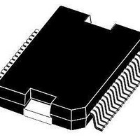
L9951 STMicroelectronics, L9951 Datasheet - Page 14

L9951
Manufacturer Part Number
L9951
Description
IC REAR DOOR ACT DVR POWERSO-36
Manufacturer
STMicroelectronics
Type
DC Motor Driverr
Datasheet
1.L9951XPTR.pdf
(36 pages)
Specifications of L9951
Applications
Automotive
Current - Supply
7mA
Voltage - Supply
7 V ~ 28 V
Operating Temperature
-40°C ~ 150°C
Mounting Type
Surface Mount
Package / Case
PowerSO-36 Exposed Bottom Pad
Operating Current
20mA
Operating Temperature Classification
Automotive
Motor Controller Type
DC Motor Driver
Package Type
PowerSO
Operating Supply Voltage (min)
7V
Operating Supply Voltage (max)
28V
Supply Current
20 mA
Mounting Style
SMD/SMT
Lead Free Status / RoHS Status
Lead free / RoHS Compliant
Available stocks
Company
Part Number
Manufacturer
Quantity
Price
Part Number:
L9951
Manufacturer:
ST
Quantity:
20 000
Part Number:
L9951XP
Manufacturer:
ST
Quantity:
20 000
Company:
Part Number:
L9951XPTR
Manufacturer:
st
Quantity:
6 966
Part Number:
L9951XPTR
Manufacturer:
ST
Quantity:
20 000
Electrical specifications
2.6
Note:
14/36
SPI - electrical characteristics
(V
voltages are referred to GND and currents are assumed positive, when the current flows into
the pin).
Table 12.
Table 13.
Value of input capacity is not measured in production test. Parameter guaranteed by design.
Table 14.
Symbol
Symbol
Symbol
t
t
t
V
hold time
I
S
I
set CSN
set CLK
t
t
CSN in
I
t
CLK in
V
I
t
CLKH
V
CLKL
set DI
EN in
inHyst
C
DI in
t
CLK
= 8 to 16 V, V
set
inH
inL
in
Input low level
Input high level
Input hysteresis
Pull up current at input CSN
Pull down current at input CLK
Pull down current at input DI
Pull down resistance at input
EN
Input capacitance at input
CLK, DI and PWM
Clock period
Clock high time
Clock low time
CSN setup time, CSN low
before rising edge of CLK
CLK setup time, CLK high
before rising edge of CSN
DI setup time
DI hold time
Delay time from standby to active mode
Inputs: CSN, CLK, PWM1/2 and DI
DI timing
Internal startup time
CC
Parameter
Parameter
Parameter
= 4.5 to 5.3 V, T
(1)
Doc ID 14173 Rev 8
j
= - 40 to 150 °C, unless otherwise specified. The
Switching from standby
to active mode. Time
until not Ready Bit goes
low.
V
CSN
V
Test condition
Test condition
Test condition
CC
V
= 3.5V V
V
V
V
V
V
V
V
V
V
V
V
CLK
DI
CC
CC
CC
= 0 to 5.3V
CC
CC
CC
CC
CC
CC
CC
= 1.5V
= 1.5V
= 5V
= 5V
= 5V
= 5V
= 5V
= 5V
= 5V
= 5V
= 5V
= 5V
CC
= 5V
1000
Min.
Min.
Min.
100
400
400
400
400
200
200
-50
1.5
0.5
10
10
Typ.
Typ.
Typ.
210
-25
2.0
3.0
80
25
25
10
L9951 / L9951XP
Max.
Max.
Max.
300
480
-10
3.5
50
50
15
Unit
Unit
Unit
µA
µA
µA
kΩ
pF
µs
ns
ns
ns
ns
ns
ns
ns
V
V
V


