STM6505SCABDG6F STMicroelectronics, STM6505SCABDG6F Datasheet
STM6505SCABDG6F
Specifications of STM6505SCABDG6F


Related parts for STM6505SCABDG6F


STM6505SCABDG6F Summary of contents
Page 1
Dual push-button Smart Reset Features ■ Dual Smart Reset push-button inputs with extended reset setup delay ■ Adjustable Smart Reset setup delay (t by external capacitor or three-state logic (product options (min.) SRC ■ ...
Page 2
Contents Contents 1 Description . . . . . . . . . . . . . . . . . . . . . . . . . . . . . . . . . . . . ...
Page 3
STM6502, STM6503, STM6504, STM6505 List of tables Table 1. Device summary . . . . . . . . . . . . . . . . . . . . . . . . . . . . . ...
Page 4
STM6502, STM6503, STM6504, STM6505 List of figures Figure 1. Logic diagrams . . . . . . . . . . . . . . . . . . . . . . . . . . . . . ...
Page 5
STM6502, STM6503, STM6504, STM6505 1 Description STM6502 has two combined Smart Reset inputs (SR0 and SR1) with delayed Smart Reset setup time (t ) programmed by an external capacitor on the SRC pin. SRC STM6503 is similar to STM6502, has ...
Page 6
Description The STM65xx devices have active-low (optionally active-high) open-drain reset (RST) output(s) with or without internal pull-up resistor or push-pull as output options, with factory- programmed or capacitor-adjustable or push-buttons defined output reset pulse duration, with or without power-on reset ...
Page 7
STM6502, STM6503, STM6504, STM6505 Table 2. Signal names Input/ Symbol output RST Output BLD Output SR0 Input SR1 Input SRE Input SRC Input TSR Input V Supply CC V Input BAT V Supply SS NC Open-drain reset output, active-low. Battery ...
Page 8
Description Figure 3. Block diagram - STM6502, STM6503, STM6504 V CC SR1 (SRE STM6504 only) (1) SR0 SRC (STM6502) TSR (STM6503, STM6504) 1. STM6504 only: SR0 and SRE are working independently. SRE is edge-triggered and has a special debounce time ...
Page 9
STM6502, STM6503, STM6504, STM6505 Figure 5. Single-button Smart Reset typical hookup Figure 6. Dual-button Smart Reset typical hookup Doc ID 16101 Rev 6 Description 9/29 ...
Page 10
Description 1.2 Pin descriptions 1.2.1 Power supply (V This pin is used to provide the power to the device and to monitor the power supply. A 0.1 µF decoupling ceramic capacitor is recommended to be connected between the V and ...
Page 11
STM6502, STM6503, STM6504, STM6505 1.2.5 Edge-triggered Smart Reset input (SRE pin) – STM6504 only The SRE pin is active-high, immediate and independent reset input that includes an edge trigger with debounce delay t Note: The triggering edge must be a ...
Page 12
Description 1.2.7 Programmable Smart Reset input delay (TSR pin) – STM6503 and STM6504 only The TSR pin allows the user to program the setup time before the push-button action is validated by the reset output controlled by different ...
Page 13
STM6502, STM6503, STM6504, STM6505 2 Typical operating characteristics Figure 10. Supply current (I -60 -40 -20 Figure 11. Smart Reset delay (t -60 -40 -20 ) vs. temperature (STM6505 2.5 2 1 ...
Page 14
Typical operating characteristics Figure 12. Reset threshold (V -60 -40 -20 Figure 13. V monitoring threshold (V BAT 1.275 1.265 1.255 1.245 1.235 1.225 -60 -40 -20 14/29 ) vs. temperature, “S” threshold option, V RST 2.99 2.97 2.95 2.93 ...
Page 15
... These are stress ratings only and operation of the device at these or any other conditions above those indicated in the operating sections of this specification is not implied. Exposure to absolute maximum rating conditions for extended periods may affect device reliability. Refer also to the STMicroelectronics SURE Program and other relevant quality documents. Table 4. ...
Page 16
DC and AC parameters 4 DC and AC parameters This section summarizes the operating measurement conditions, and the DC and AC characteristics of the device. The parameters in the DC and AC characteristics tables that follow, are derived from tests ...
Page 17
STM6502, STM6503, STM6504, STM6505 Table 6. DC and AC characteristics Symbol Parameter V Supply voltage range CC Supply current (inputs in their inactive state and t counter REC SRC is inactive) Output characteristics Reset output voltage low ...
Page 18
DC and AC parameters Table 6. DC and AC characteristics (continued) Symbol Parameter Smart Reset inputs SR0, SR1, SRE input V IL voltage low SR0, SR1, SRE input V IH voltage high Input leakage current LI(SR) and SRE ...
Page 19
STM6502, STM6503, STM6504, STM6505 . Table monitoring threshold CC V RST L (falling) M (falling) T (falling) S (falling) R (falling) Z (falling) Y (falling) W (falling) V (falling) voltage thresholds ±2.5% (–40 °C to +85 ...
Page 20
Package mechanical data 5 Package mechanical data In order to meet environmental requirements, ST offers these devices in different grades of ® ECOPACK packages, depending on their level of environmental compliance. ECOPACK specifications, grade definitions and product status are available ...
Page 21
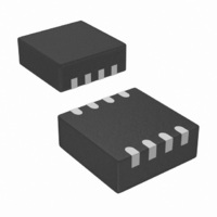
STM6502, STM6503, STM6504, STM6505 Figure 15. TDFN – 8-lead 0.75 mm, 0.5 mm pitch package outline Table 8. TDFN – 8-lead 0.75 mm, 0.5 mm pitch package mechanical data Symbol A A1 ...
Page 22
Package mechanical data Figure 16. Landing pattern - TDFN – 8-lead without thermal pad Table 9. Parameter for landing pattern - TDFN – 8-lead package Parameter L Contact length b Contact width ...
Page 23
STM6502, STM6503, STM6504, STM6505 Figure 17. Carrier tape T Top cover tape K 0 Table 10. Carrier tape dimensions Package 8.00 1.50 1.75 TDFN8 +0.30 +0.10/ ±0.10 –0.10 –0. Center ...
Page 24
Package mechanical data Figure 18. Reel dimensions D A Full radius Table 11. Reel dimensions Tape sizes A max 180 (7 inches) 24/29 STM6502, STM6503, STM6504, STM6505 40 mm min. acces hole at slot location B Tape slot ...
Page 25
STM6502, STM6503, STM6504, STM6505 Figure 19. Tape trailer/leader End Top No components cover tape 160 mm min. Figure 20. Pin 1 orientation Note: 1 Drawings are not to scale. 2 All dimensions are ...
Page 26
Part numbering 6 Part numbering Table 12. Ordering information scheme Example: Device type (1) STM6502 STM6503 (1) STM6504 STM6505 Reset (V monitoring) threshold voltage typ., falling RST L = 4.625 2.925 ...
Page 27
... STM6502, STM6503, STM6504, STM6505 7 Package marking Table 13. Package marking Part number STM6503REAADG6F STM6503SEAADG6F STM6503VEAADG6F STM6504SEABDG6F STM6505SCABDG6F STM6505RCABDG6F STM6505WCABDG6F active-low active-high with internal pull-up resistor open-drain. 2. Contact local ST sales office for availability. Figure 21. Package marking, top view t Smart SRC delay Reset V RST ...
Page 28
Revision history 8 Revision history Table 14. Document revision history Date 31-Aug-2009 06-Nov-2009 15-Jan-2010 01-Mar-2010 21-Jun-2010 09-Feb-2011 28/29 Revision 1 Initial release. Updated Applications, updated and moved to 2 Table 4, Table 6, Table Section 1.2.9, Section information, and Section ...
Page 29
... STM6502, STM6503, STM6504, STM6505 Information in this document is provided solely in connection with ST products. STMicroelectronics NV and its subsidiaries (“ST”) reserve the right to make changes, corrections, modifications or improvements, to this document, and the products and services described herein at any time, without notice. All ST products are sold pursuant to ST’s terms and conditions of sale. ...