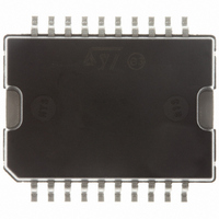
E-L9935 STMicroelectronics, E-L9935 Datasheet - Page 18

E-L9935
Manufacturer Part Number
E-L9935
Description
IC STEPPER MOTOR DVR 2PH 20PWRSO
Manufacturer
STMicroelectronics
Type
2 Phase Stepper Motor Driverr
Datasheet
1.L9935.pdf
(29 pages)
Specifications of E-L9935
Applications
Stepper Motor Driver, 2 Phase
Number Of Outputs
1
Current - Output
±1.2A
Voltage - Supply
8 V ~ 24 V
Operating Temperature
-40°C ~ 150°C
Mounting Type
Surface Mount
Package / Case
PowerSO-20 Exposed Bottom Pad
Product
Stepper Motor Controllers / Drivers
Operating Supply Voltage
14.4 V
Supply Current
4.5 mA
Mounting Style
SMD/SMT
Lead Free Status / RoHS Status
Lead free / RoHS Compliant
Voltage - Load
-
Lead Free Status / Rohs Status
Lead free / RoHS Compliant
Available stocks
Company
Part Number
Manufacturer
Quantity
Price
Functional description
5.10.1
5.11
5.11.1
18/29
Over temperature pre alarm
Typically 20K before thermal shut down takes place an over temperature pre alarm (bit7 and
bit6 low) takes place. Typically over temperature pre alarm temperature is between 150 °C
and 160 °C.
Application hints using a high resistive stepper motor
The L9935 was originally targeted on stepper chopping stepper motor application with
typical resistances of 8..12 Ω. Using motors with higher resistance will work too but
diagnosis behavior will slightly change. This paragraph shows the details that should be
taken in account using diagnosis for high resistive motors.
Startup behavior
The device has simple digital filter to avoid triggering diagnosis at a single event that could
be random noise. This digital filter needs 4 chopping pulses to settle. Using a high resistive
motor this chopping does not take place. Instead the digital filter samples each time a
polarity change takes place. So the first three response telegrams after reset may show an
’open load’ error.
Table 7.
H means check for HIGH at the error bits.
X means don’t care because filter is not yet settled.
Using 75 mA chopping immediately after stand by:
The high resistive motor can be forced to chopping operation in the low current range. This
leads to the same behavior as using a low resistive motor.
Short to V
The short to V
detected a short this flag only can be reset by reaching chopping operation or resetting the
circuit (ENN=1). For a high resistive motor this leads to the following consequence: Once a
short to VS is detected the error flag will persist even if the short is removed again until
either a reset (ENN=1) or chopping (for example in 75mA mode) has taken place. We
suggest to return to operation once a short to VS was detected by using the low current
mode to reset the flag.
Standby
1
Reverse phase (550 mA or 900 mA)
Reverse phase (550 mA or 900 mA)
Any data
Any data
st
telegram (550 mA or 900 mA)
S
detection using high resistive motors:
Input data
High and low resistive motor (error bits)
S
flag is overwritten each time the chopper comparator responds. Having
Doc ID 5198 Rev 9
High resistive motor
(error bits)
HH
XH
XH
XH
HH
-
Low resistive motor
(error bits)
HH
HH
HH
HH
HH
-
L9935


