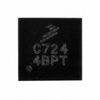
MPC17C724EP Freescale Semiconductor, MPC17C724EP Datasheet - Page 4

MPC17C724EP
Manufacturer Part Number
MPC17C724EP
Description
IC MOTOR DRVR H-BRDG DUAL 16-QFN
Manufacturer
Freescale Semiconductor
Type
Dual Half Bridge Motor Driverr
Datasheet
1.MPC17C724EP.pdf
(13 pages)
Specifications of MPC17C724EP
Applications
DC Motor Driver, Stepper Motor Driver, H Bridge
Number Of Outputs
1
Current - Output
400mA
Voltage - Load
2.7 V ~ 5.5 V
Voltage - Supply
2.7 V ~ 5.5 V
Operating Temperature
-20°C ~ 85°C
Mounting Type
Surface Mount
Package / Case
16-QFN
Operating Supply Voltage
3 V
Supply Current
0.04 mA
Mounting Style
SMD/SMT
For Use With
KIT17C724EPEVBE - KIT FOR 17C7242CH HBRIDGE PWR IC
Lead Free Status / RoHS Status
Lead free / RoHS Compliant
Available stocks
Company
Part Number
Manufacturer
Quantity
Price
Company:
Part Number:
MPC17C724EP/R2
Manufacturer:
TI
Quantity:
3 123
Company:
Part Number:
MPC17C724EPR2
Manufacturer:
GMT
Quantity:
2 046
Part Number:
MPC17C724EPR2
Manufacturer:
FREESCALE
Quantity:
20 000
Table 2. Maximum Ratings
permanent damage to the device.
4
17C724
MAXIMUM RATINGS
ELECTRICAL RATINGS
TEMPERATURE RATINGS
Notes
Power Supply Voltage (Motor Driver)
Logic Supply Voltage
Input Terminal Voltage
Driver Output Current (Continuous)
Driver Output Current (Peak)
ESD Voltage
Storage Temperature
Operating Temperature
Operating Junction Temperature
Thermal Resistance (Junction-to-Ambient)
Terminal Soldering Temperature
All voltages are with respect to ground unless otherwise noted. Exceeding these ratings may cause a malfunction or
3.
4.
5.
6.
7.
8.
9.
Normal Operation (Steady-State)
Transient Conditions
Human Body Model
Machine Model
Ambient
Single-Layer PCB Mounting
Multi-Layer PCB (2S2P) Mounting
Transient condition within 500 ms.
Continuous output current must not be exceeded and at operating junction temperature below 150°C.
Peak time is for 10 ms pulse width at 200 ms intervals.
ESD testing is performed in accordance with the Human Body Model (C
(C
Terminal soldering temperature limit is for 10 seconds maximum duration. Not designed for immersion soldering. Exceeding these limits
may cause malfunction or permanent damage to the device.
For cases using SEMI G38-87, JEDEC JESD51-2, JESD51-3, JESD51-5, single layer PCB mounting without thermal vias.
For cases using SEMI JEDEC JESD51-6, JESD51-5, JESD51-7, 2S2P PCB mounting with 4 thermal vias.
ZAP
= 200 pF, R
(6)
ZAP
(3)
= 0 Ω).
(5)
(8)
(7)
Ratings
(4)
(9)
MAXIMUM RATINGS
ZAP
= 100 pF, R
T
Symbol
V
V
V
V
R
SOLDER
T
R
I
V
M(SS)
M(PK)
V
OPK
ESD1
ESD2
θJMA
T
I
STG
T
θJA
DD
O
IN
A
J
ZAP
= 1500 Ω), and the Machine Model
Analog Integrated Circuit Device Data
- 0.3 to V
150 maximum
- 0.3 to 6.0
- 0.3 to 6.5
- 40 to 150
- 20 to 85
± 2000
Value
± 200
400
800
169
260
6.0
47
DD
Freescale Semiconductor
+ 0.3
°C/W
Unit
mA
mA
°C
°C
°C
°C
V
V
V
V


