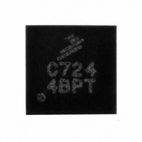
MPC17C724EP Freescale Semiconductor, MPC17C724EP Datasheet - Page 3

MPC17C724EP
Manufacturer Part Number
MPC17C724EP
Description
IC MOTOR DRVR H-BRDG DUAL 16-QFN
Manufacturer
Freescale Semiconductor
Type
Dual Half Bridge Motor Driverr
Datasheet
1.MPC17C724EP.pdf
(13 pages)
Specifications of MPC17C724EP
Applications
DC Motor Driver, Stepper Motor Driver, H Bridge
Number Of Outputs
1
Current - Output
400mA
Voltage - Load
2.7 V ~ 5.5 V
Voltage - Supply
2.7 V ~ 5.5 V
Operating Temperature
-20°C ~ 85°C
Mounting Type
Surface Mount
Package / Case
16-QFN
Operating Supply Voltage
3 V
Supply Current
0.04 mA
Mounting Style
SMD/SMT
For Use With
KIT17C724EPEVBE - KIT FOR 17C7242CH HBRIDGE PWR IC
Lead Free Status / RoHS Status
Lead free / RoHS Compliant
Available stocks
Company
Part Number
Manufacturer
Quantity
Price
Company:
Part Number:
MPC17C724EP/R2
Manufacturer:
TI
Quantity:
3 123
Company:
Part Number:
MPC17C724EPR2
Manufacturer:
GMT
Quantity:
2 046
Part Number:
MPC17C724EPR2
Manufacturer:
FREESCALE
Quantity:
20 000
Table 1. 17C724 Terminal Definitions
Analog Integrated Circuit Device Data
Freescale Semiconductor
Notes
Terminal
Number
Transparent Top View of Package
1.
2.
A functional description of each terminal can be found in the Functional Terminal Description section beginning on
6, 7
10
11
12
13
14
15
16
1
2
3
4
5
8
9
VM1 and VM2 are internally connected.
LGND, PGND1, and PGND2 are internally connected.
Terminal
PGND2
PGND1
OUT1A
OUT2A
OUT2B
OUT1B
PSAVE
LGND
Name
IN1A
IN1B
IN2B
IN2A
VM1
VM2
VDD
Function
Terminal
Ground
Ground
Ground
Output
Output
Output
Output
Power
Power
Logic
Logic
Logic
Input
Input
Input
OUT1A
Logic Input Control 1A Logic input control of OUT1A (refer to
Logic Input Control 1B Logic input control of OUT1B (refer to
Logic Input Control 2B Logic input control of OUT2B (refer to
Logic Input Control 2A Logic input control of OUT2A (refer to
Input Enable Control
H-Bridge Output 1A
H-Bridge Output 2A
H-Bridge Output 2B
H-Bridge Output 1B
Motor Driver Power
Motor Driver Power
Logic Circuit Power
1N1A
1N1B
VM1
Figure 3. 17C724 Terminal Connections
Power Ground 2
Power Ground 1
Formal Name
TERMINAL CONNECTIONS
Logic Ground
Supply 1
Supply 2
Supply
2
3
1
4
16
5
15
6
Output A of H-Bridge channel 1.
Positive power source connection for H-Bridge 1 (Motor Driver Power
Supply)
Output A of H-Bridge channel 2.
High-current power ground 2
Output B of H-Bridge channel 2.
Positive power source connection for H-Bridge 2 (Motor Driver Power
Supply)
Output B of H-Bridge channel 1.
Logic input enable control of H-Bridges to save power.
Low-current logic signal ground
High-current power ground 1
Positive power source connection for logic circuit.
14
7
(1)
(1)
13
.
.
8
12
11
10
9
IN2A
IN2B
OUT1B
VM2
(2)
(2)
Definition
.
.
(2)
.
Table 5, Truth
Table 5, Truth
Table 5, Truth
Table 5, Truth
TERMINAL CONNECTIONS
Table, page 7).
Table, page 7).
Table, page 7).
Table, page 7).
page
17C724
8.
3


