BTS555 Infineon Technologies, BTS555 Datasheet - Page 8
BTS555
Manufacturer Part Number
BTS555
Description
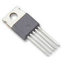
IC HISIDE PWR SWTCH TO218AB/5-1
Manufacturer
Infineon Technologies
Series
PROFET®r
Type
High Sider
Specifications of BTS555
Input Type
Non-Inverting
Number Of Outputs
1
On-state Resistance
1.9 mOhm
Current - Output / Channel
165A
Current - Peak Output
520A
Voltage - Supply
5 V ~ 34 V
Operating Temperature
-40°C ~ 150°C
Mounting Type
Through Hole
Package / Case
TO-218AB/5
Module Configuration
High Side
Peak Output Current
165A
Output Resistance
1.9ohm
Input Delay
600µs
Output Delay
200µs
Supply Voltage Range
5V To 34V
Driver Case Style
TO-218AB
No. Of Pins
5
Operating Temperature Range
-40°C To +150°C
Rohs Compliant
No
Device Type
High Side
Lead Free Status / RoHS Status
Contains lead / RoHS non-compliant
Other names
BTS555NK
SP000011266
SP000011266
Available stocks
Company
Part Number
Manufacturer
Quantity
Price
Company:

Part Number:
BTS555
Manufacturer:
INFINEON
Quantity:
3 000
Part Number:
BTS555
Manufacturer:
INFINEON/英飞凌
Quantity:
20 000
Company:
Part Number:
BTS555E3146HKSA1
Manufacturer:
INFINEON
Quantity:
12 000


Current sense status output
V
devices are connected in parallel). I
only driven by the internal circuit as long as V
5V. If you want to measure load currents up to I
R
Note: For large values of R
almost V
If you don't use the current sense output in your
application, you can leave it open.
Infineon Technologies AG
Input circuit (ESD protection)
When the device is switched off (I
between IN and GND reaches almost V
mechanical switch, a bipolar or MOS transistor with
appropriate breakdown voltage as driver.
V
Z,IS
IS
Z,IN
should be less than
V bIN
= 66 V (typ.), R
= 66 V (typ).
V
bb
bb
. See also overvoltage protection.
V IN
V
IN
Z,IN
I
IN
R
bb
IS
I
IS
= 1 k
ZD
ZD
I
V
L
(
IS
bb
M
nominal (or 1 k
)
the voltage V
/
V
5
K
Z,IS
V
ilis
IS
IN
S
.
R
= I
= 0) the voltage
IS
L
bb
/k
R bb
ilis
IS
. Use a
can reach
can be
out
V
/n, if n
IS
L(M)
- V
V bb
,
IS
>
8
Short circuit detection
Fault Condition: V
(80 ...300 µs).
Inductive and overvoltage output clamp
V
switch-off without D
-17 V typ. via V
V
the inductive load, but higher peak power dissipation in
the PROFET. In case of a floating ground with a
potential higher than 19V referring to the OUT –
potential the device will switch on, if diode DS is not
used.
Overvoltage protection of logic part
R
nominal. Note that when overvoltage exceeds 71 V typ.
a voltage above 5V can occur between IS and GND, if
R
ON
ON(CL)
bb
V
, V
R
= 120
is clamped to V
IN
Z,VIS
IN
Logic
via V
unit
are not used.
typ , V
R
V
Z1
IS
Z,IN
ZG
. Using D
IS
. With D
ON
V
Z,IN
V
S
Z,IS
Short circuit
ZG
D
Signal GND
ON(Cl)
> V
, V
detection
S
V
Z1
Logic
= V
R
OUT
ON(SC)
S
V
IS
S
gives faster deenergizing of
Z,IS
Data Sheet BTS555
= 42 V typ. At inductive load
, V
is clamped to V
OUT
= 66 V typ., R
(6 V typ.) and t> t
R
PROFET
bb
V
is clamped to V
Z,VIS
PROFET
2008-June-24
+ V
OUT
IS
OUT
+ V bb
OUT(CL)
V
V
ON
bb
OUT
V
= 1 k
ON
+ V
d(SC)
V
bb
OUT
bb
=
-
Related parts for BTS555
Image
Part Number
Description
Manufacturer
Datasheet
Request
R

Part Number:
Description:
Manufacturer:
Infineon Technologies AG
Datasheet:
Part Number:
Description:
Manufacturer:
Infineon Technologies AG
Datasheet:
Part Number:
Description:
Manufacturer:
Infineon Technologies AG
Datasheet:
Part Number:
Description:
Manufacturer:
Infineon Technologies AG
Datasheet:
Part Number:
Description:
Manufacturer:
Infineon Technologies AG
Datasheet:
Part Number:
Description:
Manufacturer:
Infineon Technologies AG
Datasheet:
Part Number:
Description:
Manufacturer:
Infineon Technologies AG
Datasheet:
Part Number:
Description:
16-bit microcontroller with 2x2 KByte RAM
Manufacturer:
Infineon Technologies AG
Datasheet:
Part Number:
Description:
NPN silicon RF transistor
Manufacturer:
Infineon Technologies AG
Datasheet:
Part Number:
Description:
NPN silicon RF transistor
Manufacturer:
Infineon Technologies AG
Datasheet:
Part Number:
Description:
NPN silicon RF transistor
Manufacturer:
Infineon Technologies AG
Datasheet:
Part Number:
Description:
NPN silicon RF transistor
Manufacturer:
Infineon Technologies AG
Datasheet:
Part Number:
Description:
Si-MMIC-amplifier in SIEGET 25-technologie
Manufacturer:
Infineon Technologies AG
Datasheet:
Part Number:
Description:
IGBT Power Module
Manufacturer:
Infineon Technologies AG
Datasheet:
Part Number:
Description:
IC for switching-mode power supplies
Manufacturer:
Infineon Technologies AG
Datasheet: