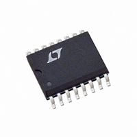
LT1336IS#TR Linear Technology, LT1336IS#TR Datasheet - Page 14

LT1336IS#TR
Manufacturer Part Number
LT1336IS#TR
Description
IC DRVR MOSF 1/2BRDG N-CH 16SOIC
Manufacturer
Linear Technology
Datasheet
1.LT1336CSPBF.pdf
(20 pages)
Specifications of LT1336IS#TR
Configuration
Half Bridge
Input Type
Differential
Delay Time
250ns
Current - Peak
1.5A
Number Of Configurations
1
Number Of Outputs
2
High Side Voltage - Max (bootstrap)
60V
Voltage - Supply
10 V ~ 15 V
Operating Temperature
-40°C ~ 85°C
Mounting Type
Surface Mount
Package / Case
16-SOIC (3.9mm Width)
Lead Free Status / RoHS Status
Contains lead / RoHS non-compliant
Available stocks
Company
Part Number
Manufacturer
Quantity
Price
applicaTions inForMaTion
LT1336
Note that for HV > 2V
is on, making the diode losses more significant than the
switch. The worst case for the diode is during a short cir-
cuit, when V
the short-circuit current almost continuously.
Figure 4 shows the LT1336 used to synchronously drive
a pair of power MOSFETs in a step-down regulator ap-
plication, where the top MOSFET is the switch and the
bottom MOSFET replaces the Schottky diode. Since both
conduction paths have low losses, this approach can result
in very high efficiency (90% to 95%) in most applications.
For regulators under 10A, using low R
MOSFETs eliminates the need for heat sinks. R
top MOSFET off when HV is applied before the 12V supply.
One fundamental difference in the operation of a step-
down regulator with synchronous switching is that it
never becomes discontinuous at light loads. The induc-
tor current doesn’t stop ramping down when it reaches
zero, but actually reverses polarity, resulting in a constant
ripple current independent of load. This does not cause
a significant efficiency loss (as might be expected) since
the negative inductor current is returned to HV when the
14
Switch On=
Switch Off=
OUT
approaches zero and the diode conducts
HV–V
V
HV
OUT
HV
OUT
REF PWM
OUT
(
Total Period
, the switch is off longer than it
Figure 4. Adding Synchronous Switching to a Step-Down Switching Regulator
OUT A
OUT A
(
Total Period
)
INTOP
INBOTTOM
DS(ON)
)
LT1336
GS
N-channel
TSOURCE
BGATEDR
TGATEDR
BGATEFB
TGATEFB
holds the
R
GS
switch turns back on. However, I
these conditions due to the recirculating currents.
The LT1336 performs the synchronous MOSFET drive in a
step-down switching regulator. A reference and PWM are
required to complete the regulator. Any voltage mode or
current mode PWM controller may be used but the LT3526
is particularly well-suited to high power, high efficiency
applications such as the 10A circuit shown in Figure 6. In
higher current regulators a small Schottky diode across
the bottom MOSFET helps to reduce reverse- recovery
switching losses.
Motor Drive Applications
In applications where rotation is always in the same di-
rection, a single LT1336 controlling a half-bridge can be
used to drive a DC motor. One end of the motor may be
connected either to supply or to ground. A motor in this
configuration is controlled by its inputs which give three
alternatives: run, free running stop (coasting) and fast
stop (“plugging” braking with the motor shorted by one
of the MOSFETs).
Whenever possible, returning one end of the motor to
ground is preferable. When the motor is returned to supply
and the boost topology is used to charge the bootstrap
capacitor, the return current from the top driver will find
its way to the high voltage rail through the top MOSFET.
Since most power supplies cannot sink current, this
HV
+
R
SENSE
+
2
R losses will occur under
1336 F04
V
OUT
1336fa


