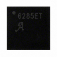
A6285EET-T Allegro Microsystems Inc, A6285EET-T Datasheet - Page 4

A6285EET-T
Manufacturer Part Number
A6285EET-T
Description
IC LED DRIVER LINEAR 32-QFN
Manufacturer
Allegro Microsystems Inc
Type
Linear (Non-Switching)r
Datasheet
1.A6285EET-T.pdf
(13 pages)
Specifications of A6285EET-T
Operating Temperature
-40°C ~ 85°C
Topology
PWM
Constant Current
Yes
Number Of Outputs
16
Internal Driver
Yes
Type - Primary
Backlight
Type - Secondary
Color, White LED
Frequency
30MHz
Voltage - Supply
3 V ~ 5.5 V
Voltage - Output
12V
Mounting Type
Surface Mount
Package / Case
32-VFQFN Exposed Pad
Current - Output / Channel
80mA
Internal Switch(s)
Yes
Led Driver Application
Display
No. Of Outputs
16
Output Current
80mA
Output Voltage
12V
Input Voltage
3V To 5.5V
Dimming Control Type
PWM
Lead Free Status / RoHS Status
Lead free / RoHS Compliant
Efficiency
-
Lead Free Status / RoHS Status
Lead free / RoHS Compliant
Other names
620-1224-5
A6285
Terminal List Table
O ¯ ¯ E ¯
GND
PE
REXT
MODE
NC
OUT0
OUT1
OUT2
OUT3
OUT4
OUT5
OUT6
OUT7
OUT8
OUT9
OUT10
OUT11
OUT12
OUT13
OUT14
OUT15
PGND
CLK
SDI
SDO
VDD
FAULT
LE
PAD
Name
5, 10, 15, 20
Number
30
29
23
27
26
12
13
14
16
17
18
19
21
22
32
24
28
25
31
11
2
3
4
6
7
8
9
1
–
Output Enable input. Active low. When O ¯ ¯ E ¯ = High, all OUTx outputs are forced OFF. When O ¯ ¯ E ¯ = Low,
ON/OFF of OUTx outputs are controlled by input data.
Logic supply ground.
Active Pull-up Enable. When connected to LED Load Supply (V
= disabled.
Reference current input/output terminal.
Logic input, Mode select. When MODE = Low, then SDI, SDO, CLK, LE are connected to ON/OFF control
logic. When MODE = High, SDI, SDO, CLK, LE are connected to dot-correction logic.
No connection. Not internally connected.
Constant current outputs.
Power ground.
Data shift clock input. Note that the internal connections are switched by input at MODE pin. At CLK↑, the
shift-registers selected by MODE shift the data.
Serial Data In. Data input of serial data interface.
Serial Data Out. Data output of serial data interface.
Logic Supply.
Error output. FAULT is open drain terminal. FAULT goes low when LOD or TSD detected.
Latch Enable input. Note that the internal connections are switched by input at the MODE pin. At LE↑, the
latches selected by MODE get new data.
Exposed pad for enhanced thermal dissipation; not connected internally, connect to power ground plane.
16-Channel Constant-Current Latched LED Driver
PGND
OUT0
OUT1
OUT2
OUT3
OUT4
SDI
with Open LED Detection and Dot Correction
NC
1
2
3
4
5
6
7
8
Pin-out Diagram
PAD
Description
24
23
22
21
20
19
18
17
SDO
PE
OUT15
OUT14
PGND
OUT13
OUT12
OUT11
LED
) = enabled, when connected to PGND
115 Northeast Cutoff
1.508.853.5000; www.allegromicro.com
Allegro MicroSystems, Inc.
Worcester, Massachusetts 01615-0036 U.S.A.
4


