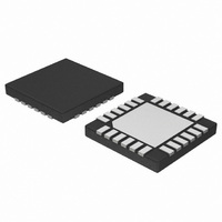
NCP5680MUTXG ON Semiconductor, NCP5680MUTXG Datasheet - Page 20

NCP5680MUTXG
Manufacturer Part Number
NCP5680MUTXG
Description
IC LED DRIVER WHT HI EFF 24-UQFN
Manufacturer
ON Semiconductor
Type
Photo Flash LED (I²C Interface)r
Datasheet
1.NCP5680MUTXG.pdf
(27 pages)
Specifications of NCP5680MUTXG
Topology
Switched Capacitor (Charge Pump)
Number Of Outputs
2
Internal Driver
No
Type - Primary
Flash/Torch
Type - Secondary
White LED
Frequency
850kHz ~ 1.15MHz
Voltage - Supply
2.7 V ~ 5.5 V
Voltage - Output
4.5 V ~ 5.3 V
Mounting Type
Surface Mount
Package / Case
24-UFQFN Exposed Pad, 24-UFQFN
Operating Temperature
-40°C ~ 85°C
Current - Output / Channel
400mA
Internal Switch(s)
Yes
Lead Free Status / RoHS Status
Lead free / RoHS Compliant
Efficiency
-
Lead Free Status / Rohs Status
Details
Available stocks
Company
Part Number
Manufacturer
Quantity
Price
Company:
Part Number:
NCP5680MUTXG
Manufacturer:
ON Semiconductor
Quantity:
2 050
Auxiliary Operation
possible the use of a permanent load connected at the Vout
pin with a 100 mA continuous load current. Two situations
shall be considered:
when the power flash is triggered: using the extra PMOS
transistor is mandatory to isolate the auxiliary load from the
power LED. In this case, a minimum 100 mF/6.3 V
capacitor is required to maintain the Vout voltage constant
during the operation.
sequence : using the PMOS transistor is not mandatory and
the auxiliary can be powered from the SuperCAP.
Thermal Consideration
manufacturers’, the forward drop of these LED can be 3 V
or less when the forward current is 100 mA and below.
Assuming that such a device is connected in the system, a
relative large amount of power will be dissipated into the
current mirrors built inside the NCP5680. Let assume that
Vf = 3.0 V @ If = 100 mA and consider the Vout was
programmed at 5.5 V. The voltage across the current mirror
will be:
The power dissipated into the current mirror will be
To control the Torch/Video mode, several registers must be preset before a flash takes place. A typical sequence is depicted here:
Typical Sequence:
Indicator
the CONFIG1 register is High. The pulse width and timer
registers are irrelevant, the time out is de−activated. The
indicator function applies solely to LED 1. The Torch/
Video mode is bypassed if it was active in the previous
phase and resumes to the previous situation when ENIND
= Low.
Select LED2
Select LED1
Select the Charge Pump Mode of Operation:
0 ³ charge pump de−activated during a flash pulse
1 ³ charge pump activated during a flash pulse
Select the Torch/Video mode
Control the charge pump: 0 ³ charge pump de−activated
Control the charge pump:
Control the pre charge mode: 0 ³ pre charge pump de−activated
Control the pre charge mode:
The power capability of the built-in charge pump makes
a - the auxiliary load is ripple sensitive and fully active
b - the auxiliary load is de-activated during a flash
Based on the data sheet published by the LED
Vom = Vout – Vf
Vom = 5.5 – 3 = 2.5 V
− send the I2C address
− select the CONFIG0 register
− activate LED1 and LED2
The indicator mode is activated when the ENIND bit in
1 ³ charge pump activated
1 ³ pre charge pump activated
CONFIG0
CONFIG1
$7C
$01
$03
http://onsemi.com
20
simultaneously, the total power dissipated by the current
mirror will be 0.50 W. In addition, the charge pump is
active during this operation to maintain Vout at the
programmed value, and an extra 400 mW will be added to
the losses. On the other hand, it is unlikely possible to
increase the PCB area large enough to significantly reduce
the thermal resistance between the QFN package and the
ambient air: generally speaking, the Rthj−a is in the range
of 40°C/W, assuming the Rthj−c negligible in comparison
to the Rthc−a. Taking all these parameters into account, the
die temperature can be calculated :
temperature, then the chip will be at 85+36 = 121°C, very
close to the maximum rating.
strongly recommended to reduce the Vout voltage to the
minimum value when the Torch/Video mode is activated.
In this case, the net voltage across the current mirror will
be limited to 4.5 – 3.0 = 1.5 V, the losses will decrease
accordingly, yielding a 113°C maximum junction
temperature under the same environment as depicted
before.
and the ILED current is controlled by the built−in current
mirror, the maximum current being 6.3 mA.
power flash or the video/torch mode having an automatic
highest priority: the indicator current for LED1 is summed
with the main current coming from either the flash or the
video/torch circuits.
Pom = Vom * If
Pom = 2.5 * 0.1 = 0.25 W
Assuming
DTj = SP x Rthj−c
DTj = (0.5 +0.4)*40 = 36°C
Assuming that the system operates under +85°C ambient
To avoid any long term fault with the system, it is
The external NMOS are deactivated (Vgs1 = Vgs2 = 0)
The indicator might be activated permanently, both the
B7
B7
−
−
−
−
−
−
B6
B6
−
−
1
−
−
−
that
B5
B5
−
−
−
0
−
−
the
B4
B4
−
−
−
−
−
−
two
B3
B3
−
−
−
−
−
−
LED
B2
B2
−
−
−
−
1
−
are
1/0
B1
B1
−
−
−
−
1
activated
1/0
B0
B0
−
−
−
−
−


