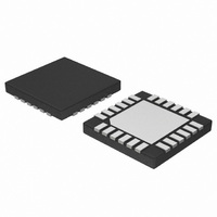
NCP5680MUTXG ON Semiconductor, NCP5680MUTXG Datasheet - Page 10

NCP5680MUTXG
Manufacturer Part Number
NCP5680MUTXG
Description
IC LED DRIVER WHT HI EFF 24-UQFN
Manufacturer
ON Semiconductor
Type
Photo Flash LED (I²C Interface)r
Datasheet
1.NCP5680MUTXG.pdf
(27 pages)
Specifications of NCP5680MUTXG
Topology
Switched Capacitor (Charge Pump)
Number Of Outputs
2
Internal Driver
No
Type - Primary
Flash/Torch
Type - Secondary
White LED
Frequency
850kHz ~ 1.15MHz
Voltage - Supply
2.7 V ~ 5.5 V
Voltage - Output
4.5 V ~ 5.3 V
Mounting Type
Surface Mount
Package / Case
24-UFQFN Exposed Pad, 24-UFQFN
Operating Temperature
-40°C ~ 85°C
Current - Output / Channel
400mA
Internal Switch(s)
Yes
Lead Free Status / RoHS Status
Lead free / RoHS Compliant
Efficiency
-
Lead Free Status / Rohs Status
Details
Available stocks
Company
Part Number
Manufacturer
Quantity
Price
Company:
Part Number:
NCP5680MUTXG
Manufacturer:
ON Semiconductor
Quantity:
2 050
ENTC: control the NTC input function
action is forwarded to the Power Flash current block.
current and the Power flash current is switched OFF when
the NTC drops below the minimum level defined by the
NTCREG register
ICHG: control the superCAP charging current during a
start up sequence
maximum (125 mA typical)
maximum (250 mA typical)
ENPH: control the photo sense
CONFIG1[7..0] Configuration register $02
RESET:
respective zero state.
CPFL:
flash sequence is on going
flash sequence.
SELFL:
cannot be fired, the ILED current is limited to
100 mA/LED.
B5 = 1 ³ the Flash mode is engaged, the flash can be fired.
I2CTRG:
flash is immediately stopped by this I2C command.
when this bit is High, unless the EXTRG bit is high. In this
case, the external Trigger pulse has the highest priority.
EXTRG:
be launched by the I2C port only
positive going pulse applied to the TRGFL pin, the duration
ENTC = 0 ³ the external NTC is de−activated and no
ENTC = 1 ³ the external NTC is biased by the internal
ICHG = 0 ³ the charging current is limited to 250 mA
ICHG = 1 ³ the charging current is limited to 350 mA
ENPH = 0 ³ the photo sense is de−activated
ENPH = 1 ³ the photo sense is activated
B7 = 1 ³ unconditionally clear all the registers to their
B6 = 0 ³ the charge pump is de−activated when a power
B6 = 1 ³ the charge pump is fully active during a power
B5 = 0 ³ the Torch / Video mode is engaged, the flash
B4 = 0 ³ when an I2C flash sequence is on going, the
B4 = 1 ³ The flash is immediately launched by the I2C
B3 = 0 ³ The TRGFL pin is de−activated, the flash can
B3 = 1 ³ The Photo Flash sequence is activated by the
RESET
RESET
B7
0
CPFL
B6
0
SELFL
B5
0
http://onsemi.com
I2CTRG
B4
10
0
CKPLS: this bit controls the LED1 & LED2 internal check
during a flash sequence
sequence
performed, during a flash sequence, the results can be read
from the STATUS register. If a fault is detected at any time
during a flash pulse, the flash sequence is immediately
stopped.
CKPRC: this bit controls the LED1 & LED2 internal
check out of a flash sequence.
performed (both LED1 and LED2), the results can be read
from the STATUS register.
of the Flash Pulse being identical to the TRGFL pulse
width. The Time out is activated. The two LED are
simultaneously powered, unless one of the two LED is not
activated, according to the CONFIG0 register setup.
CPACT:
The Vout voltage is equal to the programmed value stored
into VOUTREG register. All the LED are biased as defined
in the previous or next programming sequence. A flash can
be launched.
SACT:
de−activated. If the CPACT is Low, the Vout voltage will
be low. If the CPACT bit is High, then the Vout voltage will
be equal to the programmed value.
activated. The Vout voltage is equal to the Vbat voltage,
unless the Charge pump is activated (CPACT = 1). All the
LED are biased as defined in the previous or next
programming sequence. A power limited flash can be
launched.
ENIND:
CKPLS = 0 ³ no LED check performed during a flash
CKPRC = 1 ³ the LED check are automatically
CKPRC = 0 ³ no LED check performed
CKPRC = 1 ³ the LED check are automatically
BKL1: = LED2 control
BKL = 0 ³ LED2 de−activated
BKL = 1 ³ LED2 activated
BKL0: = LED1 control
BKL = 0 ³ LED1 de−activated
BKL = 1 ³ LED1 activated
B2 = 0 ³ the charge pump is de−activated
B2 = 1 ³ the NCP5680 and the Charge Pump are active.
B1 = 0 ³ the NCP5680 is active, but the pre−charge is
B1 = 1 ³ the NCP5680 is active, the pre−charge is
B0 = 0 ³ the Indicator function is de−activated
B0 = 1 ³ the Indicator function is activated.
EXTRG
B3
0
CPACT
B2
0
SACT
B1
0
ENIND
B0
0


