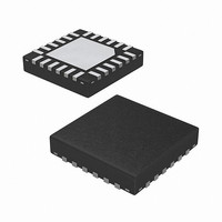
ISL97635IRZ-T Intersil, ISL97635IRZ-T Datasheet - Page 24

ISL97635IRZ-T
Manufacturer Part Number
ISL97635IRZ-T
Description
IC LED DRVR WHT/RGB BCKLGT 24QFN
Manufacturer
Intersil
Type
Backlight, White LED, RGBr
Datasheet
1.ISL97635IRZ.pdf
(28 pages)
Specifications of ISL97635IRZ-T
Topology
PWM, Step-Up (Boost)
Number Of Outputs
8
Internal Driver
Yes
Type - Primary
Automotive, Backlight
Type - Secondary
RGB, White LED
Frequency
600kHz, 1.2MHz
Voltage - Supply
6 V ~ 24 V
Voltage - Output
34.5V
Mounting Type
Surface Mount
Package / Case
24-VQFN
Operating Temperature
-40°C ~ 85°C
Current - Output / Channel
35mA
Internal Switch(s)
Yes
Efficiency
91%
Lead Free Status / RoHS Status
Lead free / RoHS Compliant
Components Selections
According to the inductor Voltage-Second Balance principle,
the change of inductor current during the switching regulator
On-time is equal to the change of inductor current during the
switching regulator Off-time. Since the voltage across an
inductor is as shown in Equation 16:
and ΔI
where D is the switching duty cycle defined by the turn-on
time over the switching period. V
voltage that can be neglected for approximation.
Rearranging the terms without accounting for V
boost ratio and duty cycle respectively as Equations 18
and 19:
Input Capacitor
Switching regulators require input capacitors to deliver peak
charging current and to reduce the impedance of the input
supply. This reduces interaction between the regulator and
input supply, thereby improving system stability. The high
switching frequency of the loop causes almost all ripple
current to flow in the input capacitor, which must be rated
accordingly.
A capacitor with low internal series resistance should be
chosen to minimize heating effects and improve system
efficiency, such as X5R or X7R ceramic capacitors, which
offer small size and a lower value of temperature and voltage
coefficient compared to other ceramic capacitors.
In Boost mode, input current flows continuously into the
inductor; AC ripple component is only proportional to the rate
of the inductor charging, thus, smaller value input capacitors
may be used. It is recommended that an input capacitor of at
least 10µF be used. Ensure the voltage rating of the input
capacitor is suitable to handle the full supply range.
V
(
V
D
V
L
O
Bit 7 (R/W)
I
=
–
⁄
=
REGISTER 0x09
V
CH7
(
0 ) L ⁄
BIT ASSIGNMENT
V
L
I
L
=
O
×
@ On = ΔI
1
ΔI
–
×
⁄
CH[7..0]
V
L
(
D
1 D
I
⁄
) V
Δt
×
–
⁄
Bit 6 (R/W)
t
S
O
)
=
CH6
L
(
@ Off, therefore:
V
O
–
V
D
Bit 5 (R/W)
OUTPUT CHANNEL REGISTER
–
24
V
CH5
I
CH7 = Channel 7, CH6 = Channel 6 and so on
)
D
⁄
L
is Schottky diode forward
×
1 (
–
Bit 4 (R/W)
BIT FIELD DEFINITIONS
D )
CH4
FIGURE 29. OUTPUT CHANNEL REGISTER
×
t
S
D
gives the
(EQ. 16)
(EQ. 17)
(EQ. 18)
(EQ. 19)
Bit 3 (R/W)
CH3
ISL97635
Bit 2 (R/W)
IL
CH2
Inductor
The selection of the inductor should be based on its
maximum current (I
(DCR), EMI susceptibility (shielded vs unshielded), and size.
Inductor type and value influence many key parameters,
including ripple current, current limit, efficiency, transient
performance and stability.
The inductor’s maximum current capability must be
adequate enough to handle the peak current at the worst
case condition. If an inductor core is chosen with too low a
current rating, saturation in the core will cause the effective
inductor value to fall, leading to an increase in peak to
average current level, poor efficiency and overheating in the
core. The series resistance, DCR, within the inductor causes
conduction loss and heat dissipation. A shielded inductor is
usually more suitable for EMI susceptible applications, such
as LED backlighting.
The peak current can be derived from the voltage across the
inductor during the Off-period, as expressed in Equation 20:
The choice of 85% is just an average term for the efficiency
approximation. The first term is the average current, which is
inversely proportional to the input voltage. The second term
is the inductor current change, which is inversely
proportional to L and f
frequency and minimum input voltage on which the system
operates, the inductor I
given inductor size, usually the larger the inductance, the
higher the series resistance because of the extra winding of
the coil. Thus, the higher the inductance, the lower the peak
current capability. The ISL97635 current limit should also
have to be taken into account.
Output Capacitors
The output capacitor acts to smooth the output voltage and
supplies load current directly during the conduction phase of
the power switch. Output ripple voltage consists of the
discharge of the output capacitor for I
and the voltage drop due to flowing through the ESR of the
peak
=
(
V
Bit 1 (R/W)
O
×
CH1
I
O
)
⁄
(
85%
SAT
SW
Bit 0 (R/W)
) characteristics, power dissipation
SAT
×
. As a result, for a given switching
V
CH0
I
must be chosen carefully. At a
)
+
1 2 V
⁄
[
I
×
LPEAK
(
V
O
–
during FET On
V
I
)
December 22, 2008
⁄
L (
×
V
FN6434.2
(EQ. 20)
O
×
f
SW
)


