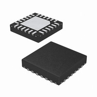
ISL97635IRZ-T Intersil, ISL97635IRZ-T Datasheet - Page 23

ISL97635IRZ-T
Manufacturer Part Number
ISL97635IRZ-T
Description
IC LED DRVR WHT/RGB BCKLGT 24QFN
Manufacturer
Intersil
Type
Backlight, White LED, RGBr
Datasheet
1.ISL97635IRZ.pdf
(28 pages)
Specifications of ISL97635IRZ-T
Topology
PWM, Step-Up (Boost)
Number Of Outputs
8
Internal Driver
Yes
Type - Primary
Automotive, Backlight
Type - Secondary
RGB, White LED
Frequency
600kHz, 1.2MHz
Voltage - Supply
6 V ~ 24 V
Voltage - Output
34.5V
Mounting Type
Surface Mount
Package / Case
24-VQFN
Operating Temperature
-40°C ~ 85°C
Current - Output / Channel
35mA
Internal Switch(s)
Yes
Efficiency
91%
Lead Free Status / RoHS Status
Lead free / RoHS Compliant
DC Brightness Control Register (0x07)
The DC Brightness Control Register 0x07 allows users to
have additional dimming flexibility by:
1. Effectively achieving 16 bits of dimming control when DC
dimming is combined with PWM dimming or,
2. Achieving visual or audio noise free 8-bit DC dimming
over potentially noisy PWM dimming.
The bit assignment is shown in Figure 27. All of the bits in
this Register can be read or write. Steps 0 to 255 represent
the linear steps of current adjustment in DC on the fly. It can
also be considered as the peak current factory calibration
feature to account for various LED production batch
variations, but external EEPROM settings storing and
restoring are required.
• An SMBus Write Byte cycle to Register 0x07 sets the
• An SMBus Read Byte cycle to Register 0x07 returns the
• Default value for Register 0x07 is 0xFF.
Configuration Register (0x08)
The Configuration Register allows users to set 2 levels of
channel Short-Circuit thresholds or disable it. It also allows
RESERVED RESERVED RESERVED RESERVED RESERVED
Bit 7 (R/W)
Bit 7 (R/W)
brightness level in DC only.
current DC brightness level.
BRTDC7
REGISTER 0x07
REGISTER 0x08
BIT ASSIGNMENT
BIT ASSIGNMENT
BRTDC[7..0]
VSC[1..0]
FSW[2]
Bit 6 (R/W)
Bit 6 (R/W)
BRTDC6
DC BRIGHTNESS CONTROL REGISTER
Bit 5 (R/W)
CONFIGURATION REGISTER
Bit 5 (R/W)
BRTDC5
23
= 256 steps of DC brightness levels
FIGURE 27. DESCRIPTIONS OF DC BRIGHTNESS CONTROL REGISTER
2 levels of Short-Circuit Thresholds (1 = 8V, 0 = 3.1V, accuracy ±15%)
2 levels of Switching Frequencies (1 = 1,200kHz, 0 = 600kHz)
FIGURE 28. DESCRIPTIONS OF CONFIGURATION REGISTER
Bit 4 (R/W)
BIT FIELD DEFINITIONS
Bit 4 (R/W)
BRTDC4
BIT FIELD DEFINITIONS
Bit 3 (R/W)
Bit 3 (R/W)
BRTDC3
ISL97635
Bit 2 (R/W)
Bit 2 (R/W)
BRTDC2
FSW
users to set the boost conversion switching frequency
between 1.2MHz and 600kHz.
The bit assignment is shown in Figure 28. The default value
for Register 0x08 is 0xFF
Output Channel Mask/Fault Readout Register
(0x09)
This register can be read or write; the bit position
corresponds to the channel. For example, bit 0 corresponds
to Ch0 and bit 6 corresponds to Ch6 and so on. Writing data
to this register, it enables the channels of interest. When
reading data from this register, any disabled channel and
any faulted out channel will read as 0. This allows the user to
determine which channel is faulty and optionally not enabling
it in order to allow the rest of the system to continue to
function. Additionally, a faulted out channel can be disabled
and re-enabled in order to allow a retry for any faulty channel
without having to power-down the other channels.
The bit assignment is shown in Figure 29. The default for
Register 0x09 is 0xFF.
Bit 1 (R/W)
Bit 1 (R/W)
BRTDC1
VSC1
Bit 0 (R/W)
Bit 0 (R/W)
BRTDC0
VSC0
December 22, 2008
FN6434.2


