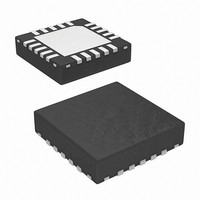
ISL97675IRZ-TK Intersil, ISL97675IRZ-TK Datasheet - Page 14

ISL97675IRZ-TK
Manufacturer Part Number
ISL97675IRZ-TK
Description
IC LED DVR PWM CTRL 4CH 20QFN
Manufacturer
Intersil
Type
Backlight, White LEDr
Datasheet
1.ISL97675IRZ-TK.pdf
(20 pages)
Specifications of ISL97675IRZ-TK
Topology
PWM, Step-Up (Boost)
Number Of Outputs
4
Internal Driver
Yes
Type - Primary
Backlight
Frequency
600kHz, 1.2MHz
Voltage - Supply
4.5 V ~ 26 V
Voltage - Output
45V
Mounting Type
Surface Mount
Package / Case
20-VQFN
Operating Temperature
-40°C ~ 85°C
Current - Output / Channel
30mA
Internal Switch(s)
Yes
Efficiency
92%
Lead Free Status / RoHS Status
Lead free / RoHS Compliant
Other names
ISL97675IRZ-TKTR
PWMI
ILED1
ILED2
ILED3
ILED4
ILED1
where (255/N) in Equation 6 and Equation 7 can only be
integer because the PWM dimming is controlled by an
internal 8-bit digital counter. As a result, any decimal
value of (255/N) will be discarded. For example for N = 4,
(255/N) = 63, thus:
where t
of active channels. The ISL97675 will detect the numbers
of active channels automatically and is illustrated in
Figure 23 for 4-channel.
FIGURE 23. 4 EQUAL PHASE CHANNELS PHASE SHIFT
PWM Dimming Frequency Adjustment
The dimming frequency is set by an external resistor at
the RFPWM/DirectPWM pin to GND:
where FPWM is the desirable PWM dimming frequency
and R
RFPWM/DirectPWM if direct PWM dimming is used, see
Table 1 for clarification.
The PWM dimming frequency can be set or applied up to
30kHz with duty cycle from 0.4% to 100%. The lower
limit of 0.4% is the result of 8-bit digitizer resolution.
Direct PWM Dimming
The ISL97675 can also operate in direct PWM dimming
mode such that the output follows the input PWM signal
without phase shifting. To use Direct PWM mode, users
should float RFPWM/DirectPWM pin. The input PWM
frequency should be limited to 30kHz and the minimum
duty cycle be calculated by the following Equation 10:
Min Duty Cycle
F
t
t
D1
D2
PWM
=
=
60%
t
t
FPWM
FPWM
FPWM
=
FPWM
t
6.66
----------------------- -
RFPWM
t
D1
PWMIN
= Fixed Delay with Integer only while the decimal value
is the setting resistor. Do not bias
will be discarded (e.g. 63.75 = 63)
×
×
×10
ILLUSTRATION
is the sum of t
=
--------- -
255
--------- -
255
63
66
t
7
t
350ns Input PWM Frequency
D1
D1
t
FPWM
60%
t
ON
t
D1
(t
×
PWMOUT
t
D1
40%
14
t
OFF
)
t
ON
D2
and t
OFF
. N is the number
(EQ. 10)
(EQ. 8)
(EQ. 9)
ISL97675
For example, for a 200 Hz input PWM frequency, the
minimum duty cycle is:
Min DC
Table 1 shows the PWM Dimming with Phase Shift and
Direct PWM Dimming configurations.
Switching Frequency
When the FSW/PhaseShift pin is biased from VDDIO with
a resistor divider R
frequency and phase shift function will change according
to the following FSW/PhaseShift levels shown in Table 2
with the recommended R
Inrush Control and Soft-Start
The ISL97675 has separate built-in independent inrush
control and soft-start functions. The inrush control function
is built around the short circuit protection FET, and is only
available in applications which include this device.
After an initial delay from the point where the master
Fault Protection FET is turned on, it is assumed that
inrush has completed. At this point, the boost regulator
will begin to switch and the current in the inductor will
ramp-up. The current in the boost power switch is
monitored and the switching is terminated in any cycle
where the current exceeds the current limit. The
ISL97675 includes a soft-start feature where this current
limit starts at a low value (275mA). This is stepped up to
the final 2.2A current limit in 7 further steps of 275mA.
These steps will happen over at least 8ms, and will be
extended at low LED PWM frequencies if the LED duty
cycle is low. This allows the output capacitor to be
charged to the required value at a low current limit and
prevents high input current for systems that have only a
low to medium output current requirement.
Connects with
Resistor
Floating
0 ~ 0.25 * VDDIO
0.25 * VDDIO ~ 0.5 * VDDIO
0.5 * VDDIO ~ 0.75 * VDDIO
0.75 * VDDIO ~ VDDIO
DIRECTPWM
RFWM/
SHIFT LEVEL
FSW/PHASE
=
350ns
×
200Hz
PWM Dimming
with frequency
adjust
DirectPWM
without
frequency adjust
UPPER
FUNCTION
=
TABLE 1.
0.007%
TABLE 2.
SWITCHING
and R
FREQUENCY
UPPER
600kHz
600kHz
1.2MHz
1.2MHz
LOWER
and R
PHASE
SHIFT
Yes
No
PHASE
, the switching
SHIFT
LOWER
Yes
Yes
No
No
Resolution
R
values
Dimming
(kΩ)
Open
UPPER
150
100
0
8-bit
N/A
May 19, 2010
(EQ. 11)
.
R
FN7630.0
(kΩ)
Open
LOWER
100
150
0


