ISL97675IRZ-TK Intersil, ISL97675IRZ-TK Datasheet - Page 13

ISL97675IRZ-TK
Manufacturer Part Number
ISL97675IRZ-TK
Description
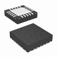
IC LED DVR PWM CTRL 4CH 20QFN
Manufacturer
Intersil
Type
Backlight, White LEDr
Datasheet
1.ISL97675IRZ-TK.pdf
(20 pages)
Specifications of ISL97675IRZ-TK
Topology
PWM, Step-Up (Boost)
Number Of Outputs
4
Internal Driver
Yes
Type - Primary
Backlight
Frequency
600kHz, 1.2MHz
Voltage - Supply
4.5 V ~ 26 V
Voltage - Output
45V
Mounting Type
Surface Mount
Package / Case
20-VQFN
Operating Temperature
-40°C ~ 85°C
Current - Output / Channel
30mA
Internal Switch(s)
Yes
Efficiency
92%
Lead Free Status / RoHS Status
Lead free / RoHS Compliant
Other names
ISL97675IRZ-TKTR
For example, if the maximum required LED current
(I
Equation 4:
PWM Control
The ISL97675 has a high speed 8-bit digitizer that
decodes an incoming PWM signal and converts it into
four channels of 8-bit PWM current with a phase shift
function that will be described later. During the PWM On
period, the LED peak current is defined by the value of
R
is controlled by I
percent as:
When the PWM input = 0, all channels are disconnected
and the I
The PWM dimming frequency is adjusted by a resistor at
the RFPWM pin, which will be described in “PWM
Dimming Frequency Adjustment” on page 14.
FIGURE 20. PHASE SHIFT 4-Ch LED DRIVER WITH 10%
FIGURE 19. CONVENTIONAL 4-Ch LED DRIVER WITH
R
I
LED ave
ISET
ISET
LED(max)
ILED_Total_20mA
(
ILED_Total_80mA
resistor, the average LED current of each channel
=
)
(
ILED1-20mA
ILED2-20mA
ILED3-20mA
ILED4-20mA
392
LED
=
) is 20mA, rearranging Equation 3 yields
ILED1-20mA
ILED2-20mA
ILED3-20mA
ILED4-20mA
I
LEDmax
) 0.02
PWM DIMMING CHANNEL CURRENT
(UPPER) AND TOTAL CURRENT (LOWER)
10% PWM DIMMING CHANNEL CURRENT
(UPPER) AND TOTAL CURRENT (LOWER)
is guaranteed to be <10µA in this state.
⁄
LEDmax
=
×
19.6kΩ
PWM
and the PWM duty cycle in
13
5
5
TIME (ms)
TIME (ms)
10
10
15
(EQ. 5)
(EQ. 4)
ISL97675
Phase Shift Control
The ISL97675 is capable of delaying the phase of each
current source. Conventional LED drivers pose the worst
load transients to the boost circuit by turning on all
channels simultaneously as shown in Figure 19. In
contrast, the ISL97675 phase shifts each channel by
turning them on once during each PWM dimming period
as shown in Figure 20. At each dimming duty cycle
except at 100%, the sum of the phase shifted channel
currents will be less than a conventional LED driver as
shown in Figure 20 and 22. Equal phase means there is
fixed delay between channels and such delay can be
calculated as:
FIGURE 22. EQUAL PHASE SHIFT LED DRIVERpwm
t
t
FIGURE 21. CONVENTIONAL LED DRIVER PWM DIMMING
D1
D2
ILED_Total_40mA
ILED_Total_80mA
=
=
t
------------------ - x 255
t
------------------ - x 255
ILED4-20mA
ILED3-20mA
ILED2-20mA
ILED1-20mA
FPWM
FPWM
(
ILED4-20mA
ILED3-20mA
ILED2-20mA
ILED1-20mA
255
255
)
CHANNEL AND TOTAL CURRENT AT 50%
DUTY CYCLE
DIMMING CHANNEL AT 50% DUTY CYCLE
⎛
⎝
⎛
⎝
(
--------- -
N
⎞
⎠
)
–
(
N 1
–
)
⎛
⎝
255
--------- -
N
5
5
⎞
⎠
⎞
⎠
TIME (ms)
TIME (ms)
10
10
May 19, 2010
FN7630.0
(EQ. 6)
(EQ. 7)


