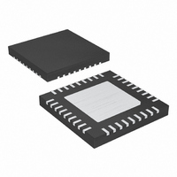
MAX5954LETX+T Maxim Integrated Products, MAX5954LETX+T Datasheet - Page 19

MAX5954LETX+T
Manufacturer Part Number
MAX5954LETX+T
Description
IC PCI EXP/HOT-PLUG CTRLR 36TQFN
Manufacturer
Maxim Integrated Products
Type
Hot-Swap Controllerr
Datasheet
1.MAX5954AETX.pdf
(22 pages)
Specifications of MAX5954LETX+T
Applications
General Purpose, PCI Express
Internal Switch(s)
No
Voltage - Supply
3.3V, 12V
Operating Temperature
-40°C ~ 85°C
Mounting Type
Surface Mount
Package / Case
36-WFQFN Exposed Pad
Mounting Style
SMD/SMT
Lead Free Status / RoHS Status
Lead free / RoHS Compliant
Single PCI Express, Hot-Plug
Controller
t
fault must remain for the MAX5954 to disable the main
or auxiliary outputs. Program the fault timeout period
(t
t
The t
according to the total capacitance load connected to
12G and 3.3G. To properly power-up the main supply
outputs, the following constraints need to be taken:
where t
1) I
2) V
3) C
Maximum and minimum values for R
500Ω, respectively. Leave TIM floating for a default
t
t
outputs reach their power-good threshold to when
PWRGD pulls low. Program the power-on-reset timeout
period (t
PORADJ to GND. t
lowing equation:
Table 3. Component Manufacturers
FAULT
FAULT
FAULT
POR_HL
FAULT
Setting the Fault Timeout Period (t
CHG
FAULT
GATE
LOAD
can be calculated by the following equation:
) by connecting a resistor (R
of 11ms.
SU
is the time an overcurrent or overtemperature
Sense Resistor
COMPONENT
POR
is the time from when the gate voltages of all
= 5µA.
MOSFETs
= 2 x t
= 18.4V for 12G and V
is the total capacitance load at the gate.
programmed time duration must be chosen
t
) by connecting a resistor (R
POR_HL
t
FAULT
Applications Information
t
FAULT
SU
______________________________________________________________________________________
POR_HL
Setting the Power-On-Reset
≥
= 2.5µs / Ω x R
= 166ns / Ω x R
V
Timeout Period (t
and where:
GATE
can be calculated by the fol-
I
CHG
×
C
LOAD
GATE
TIM
International Rectifier
MANUFACTURER
PORADJ
TIM
Vishay-Siliconix
) from TIM to GND.
TIM
Vishay-Dale
= 9.4V for 3.3G.
Fairchild
Motorola
are 500kΩ and
IRC
PORADJ
POR_HL
FAULT
) from
)
)
Maximum and minimum values for R
and 500Ω, respectively. Leave PORADJ floating for a
default t
Select the external n-channel MOSFET according to the
applications current requirement. Limit the switch
power dissipation by choosing a MOSFET with an
R
full load. High R
there are pulsed loads. High R
external undervoltage fault at full load. Determine the
MOSFET’s power rating requirement to accommodate a
short-circuit condition on the board during startup. Table
3 lists MOSFETs and sense-resistor manufacturers.
External capacitance can be added from the gate of
the external MOSFETs to GND to slow down the dV/dt
of the 12V and 3.3V outputs.
Large capacitive loads at the 12V output, the 3.3V out-
put, and the 3.3V auxiliary output can cause a problem
when inserting discharged PCI cards into live back-
planes. A fault occurs if the time needed to charge the
capacitance of the board is greater than the typical
startup time (2 x t
large capacitive loads due to their adjustable startup
times and adjustable current-limit thresholds. Calculate
the maximum load capacitance as follows:
V
3.3V auxiliary output.
OUT
DS_ON
402-564-3131
704-264-8861
888-522-5372
310-322-3331
602-244-3576
is either the 3.3V output, the 12V output, or the
Additional External Gate Capacitance
POR
PHONE
low enough to have a minimum voltage drop at
—
of 160ms.
DS_ON
C
FAULT
Maximum Load Capacitance
LOAD
). The MAX5954 can withstand
causes larger output ripple if
<
t
Component Selection
SU
www.irf.com
www.vishay.com
www.irctt.com
www.fairchildsemi.com
www.mot-sps.com/ppd/
www.vishay.com
V
DS_ON
OUT
×
I
LIM
PORADJ
WEBSITE
can also trigger an
are 500kΩ
19


