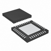
MAX5954LETX+T Maxim Integrated Products, MAX5954LETX+T Datasheet - Page 13

MAX5954LETX+T
Manufacturer Part Number
MAX5954LETX+T
Description
IC PCI EXP/HOT-PLUG CTRLR 36TQFN
Manufacturer
Maxim Integrated Products
Type
Hot-Swap Controllerr
Datasheet
1.MAX5954AETX.pdf
(22 pages)
Specifications of MAX5954LETX+T
Applications
General Purpose, PCI Express
Internal Switch(s)
No
Voltage - Supply
3.3V, 12V
Operating Temperature
-40°C ~ 85°C
Mounting Type
Surface Mount
Package / Case
36-WFQFN Exposed Pad
Mounting Style
SMD/SMT
Lead Free Status / RoHS Status
Lead free / RoHS Compliant
Single PCI Express, Hot-Plug
Controller
The MAX5954 hot-plug controller is designed for PCI
Express applications. The device provides hot-plug
control for 12V, 3.3V, and 3.3V auxiliary supplies of a
single PCI Express slot. The MAX5954’s logic
inputs/outputs allow interfacing directly with the system
hot-plug-management controller or through an SMBus
with an external I/O expander. An integrated
debounced attention switch and present-detect signals
are included to simplify system design.
The MAX5954 drives two external n-channel MOSFETs
to control the 12V and 3.3V main outputs. The 3.3V aux-
iliary output is controlled through an internal 0.3Ω
n-channel MOSFET. An internal charge pumps pro-
vides a gate drive for the 12V output while the gate
drive of the 3.3V output is driven by the 12V input sup-
ply. The 3.3V auxiliary output is completely indepen-
dent from the main outputs with its own charge pump.
At power-up, the MAX5954 keeps all of the external
MOSFETs off until all supplies rise above their respec-
tive UVLO thresholds. The device keeps the internal
MOSFET off only until the 3.3VAUXIN supply rises
above its UVLO threshold. Upon a turn-on command,
the MAX5954 enhances the external and internal
MOSFETs slowly with a constant gate current to limit
the power-supply inrush current. The MAX5954 actively
limits the current of all outputs at all times and shuts
down if an overcurrent condition persists for longer
than a programmable overcurrent timeout. Thermal-
protection circuitry also shuts down all outputs if the die
temperature exceeds +150°C. After an overcurrent or
overtemperature fault condition, the MAX5954L latches
PIN
25
28
31
32
33
34
35
36
OUTPUT
PORADJ
NAME
INPUT
PGND
12VIN
GND
TIM
T2
______________________________________________________________________________________
Detailed Description
Test Input. Connect T2 to GND.
Overcurrent Timeout Programming Input. Connect a resistor between 500Ω and 500kΩ from TIM to GND
to program t
Digital Output. 4ms debounced digital output of INPUT.
Digital Logic Gate Input
12V Supply Input. V
charge pump that drives the gate of the MOSFET connected to 12G.
Ground
Power Ground. Connect externally to GND.
Power-On-Reset Programming Input. Connect a resistor between 500Ω and 500kΩ from PORADJ to GND
to program the POR timing. Leave floating for a default value of 160ms.
FAULT
. Leave TIM floating for a default timeout of 11ms.
12VIN
drives the gate of the MOSFET connected to 3.3G. 12VIN powers an internal
off while the MAX5954A automatically restarts after a
restart time delay.
The power requirement for PCI Express connectors is
defined by the PCI Express card specification and
summarized in Table 1.
The main supply outputs can become active only after
all the following events have occurred:
•
•
•
•
The auxiliary supply output is made available only after
the following events have occurred:
•
•
•
The FON input overrides all other control signals and
turns on the PCI Express slot when driven low, as long
as the UVLO thresholds have been reached. Table 2
summarizes the logic conditions required for startup.
The auxiliary supply input powers the internal control
logic and analog references of the MAX5954, so the
main supplies cannot be enabled if V
present.
When an output is enabled, a programmable startup
timer (t
The value of t
FUNCTION
V
V
threshold
ON is driven high
PRES-DET is low for more than 5ms
V
AUXON is driven high
PRES-DET is low for more than 5ms
3.3VAUXIN
3.3VAUXIN
12VIN
SU
) begins to count the startup time duration.
Pin Description (continued)
and V
SU
is above its UVLO threshold
is above its UVLO threshold
is set to 2x the fault timeout period
3.3S+
are both above their UVLO
3.3VAUXIN
Startup
is not
13


