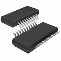
LTC4244CGN-1#PBF Linear Technology, LTC4244CGN-1#PBF Datasheet - Page 19

LTC4244CGN-1#PBF
Manufacturer Part Number
LTC4244CGN-1#PBF
Description
IC CTRLR HOTSWAP PCI 20-SSOP
Manufacturer
Linear Technology
Type
Hot-Swap Controllerr
Datasheet
1.LTC4244IGN-1PBF.pdf
(28 pages)
Specifications of LTC4244CGN-1#PBF
Applications
CompactPCI™
Internal Switch(s)
No
Voltage - Supply
3.3V, 5V, ±12V
Operating Temperature
0°C ~ 70°C
Mounting Type
Surface Mount
Package / Case
20-SSOP (0.154", 3.91mm Width)
Lead Free Status / RoHS Status
Lead free / RoHS Compliant
APPLICATIO S I FOR ATIO
BD_SEL# voltage drops below 4.4V thus causing the bus
switch OE to be pulled high by Q2.
The CompactPCI specification assumes that there is a
diode to 3.3V on the circuit that is driving the BD_SEL# pin.
The 1.2k resistor pull-up to 5V
clamped by the diode to 3.3V. If the BD_SEL# pin is being
driven high, the actual voltage on the pin will be approxi-
mately 3.9V. This is still above the high TTL threshold of
the LTC4244 OFF/ON pin, but low enough for Q2 to disable
the bus switches and thus disconnect the 10k precharge
resistors from the I/O lines. Since the power to the bus
switch is derived from a front-end power plane, a 100
resistor should be placed in series with the power supply
of the bus switch.
When the plug-in card is removed from the connector, the
BD_SEL# connection is broken first, and the BD_SEL#
voltage pulls up to 5V
re-enables the bus switch, and the precharge resistors are
again connected to the LTC4244 PRECHARGE pin for the
remainder of the extraction process.
TIMER/Auxiliary V
Once the TIMER pin voltage has ramped to within 1.6V of
12V
the 12V
continue to draw power from the charge stored on the
TIMER pin capacitor until the internal V
below its undervoltage lockout threshold or the 12V
supply voltage recovers, whichever happens first.
IN
, the auxiliary V
IN
supply voltage collapses, the LTC4244 will
LONG 5V
GROUND
5V
CC
U
IN
CC
CONNECTOR
BACKPLANE
. This causes Q2 to turn off, which
Z4: SMAJ5.0A
*ADDITIONAL PINS OMITTED FOR CLARITY
function is enabled. In the event
U
IN
on the plug-in card will be
CONNECTOR
BACKPLANE
PCB EDGE
W
Figure 10. No 3.3V Supply Application Circuit
Z4
CC
5V
8
node drops
IN
GND
U
3.3V
17
IN
3.3V
IN
SENSE
16
5V
Other CompactPCI Applications
The LTC4244-1 is designed for CompactPCI designs
where the –12V supply is not being used on the plug-in
board. The V
and V
pin should be connected to GND and the V
floating if a –12V output is not needed.
If no 3.3V supply input is required, Figure 10 illustrates
how the LTC4244 should be configured: 3.3V
3.3V
5V
For applications where the BD_SEL# connector pin is
typically connected to ground on the backplane, the circuit
in Figure 11 allows the LTC4244 to be reset simply by
pressing a pushbutton switch on the CPCI plug in board.
This arrangement eliminates the requirement to extract
and reinsert the CPCI board in order to reset the LTC4244’s
circuit breaker.
IN
BD_SEL#
GROUND
13
OUT
0.007
IN
R2
EE
.
LTC4244*
are connected to 5V
5V
CONNECTOR
BACKPLANE
Figure 11. BD_SEL# Pushbutton Toggle Switch
*ADDITIONAL PINS OMITTED FOR CLARITY
circuit breaker functions are disabled. The V
SENSE
14
EEOUT
IRF7457
GATE
Q2
15
R4
10
CONNECTOR
BACKPLANE
PCB EDGE
3.3V
power good comparator, V
LTC4244/LTC4244-1
OUT
18
5V
IN
PUSHBUTTON
OUT
3
and 3.3V
R5
1k
SWITICH
0.25W
100
4244 F10
0.33 F
C1
5V
OUT
OUT
V(I/O)
is connected to
1.2k
EEOUT
1k
5
8
SENSE
EEIN
OFF/ON
GND
19
LTC4244*
pin left
UVL,
42441f
EEIN
and
4244 F11


