MAX5916AEUI+ Maxim Integrated Products, MAX5916AEUI+ Datasheet - Page 14

MAX5916AEUI+
Manufacturer Part Number
MAX5916AEUI+
Description
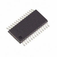
IC HOT-SWAP CTRLR DUAL 28-TSSOP
Manufacturer
Maxim Integrated Products
Type
Hot-Swap Controllerr
Datasheet
1.MAX5916EUI.pdf
(25 pages)
Specifications of MAX5916AEUI+
Applications
PCI 2.2 Server
Internal Switch(s)
No
Voltage - Supply
10.8 V ~ 13.2 V
Operating Temperature
-40°C ~ 85°C
Mounting Type
Surface Mount
Package / Case
28-TSSOP
Lead Free Status / RoHS Status
Lead free / RoHS Compliant
UVLO prevents these devices from turning on
internal/external MOSFETs until the input voltage exceeds
the lockout threshold. The UVLO protects the MOSFETs
from insufficient gate-drive voltage. Figure 2 shows that if
an input undervoltage condition exists for more than
t
low immediately. The time delay t
edge delayed and acts as a deglitch.
When a fault is detected on one of the main outputs, the
MAX5915/MAX5915A/MAX5916/MAX5916A disable the
channel outputs after t
the output voltages fall below their output undervoltage
threshold or any of the output currents exceed their out-
put overcurrent threshold. PGOOD_ pulls low if a fault
persists for more than t
disabled after t
able with a response time of 1.5ms (t
MAX5915A/MAX5916A offer a response time of 100ns
(t
nel remains on and PGOOD_ pulls high immediately.
Dual PCI 2.2 Hot-Swap Controllers
Figure 2. Input UVLO Fault Management in the MAX5915/MAX5915A/MAX5916/MAX5916A
14
DEG,UVLO
RESP2
TIMING NOT TO SCALE
3.3VAUXO_
3.3VAUXIN
______________________________________________________________________________________
AUXON_
PGOOD_
+12VO_
-12VO_
+12VIN
3.3VO_
5VO_
). If the fault is removed before t
ON_
, the outputs are disabled and PGOOD_ goes
+12V UVLO THRESHOLD
t
DEG.UVLO
DELAY
Input Undervoltage Lockout
. The MAX5915/MAX5916 are avail-
DELAY
RESP
. The channel with the fault is
. A fault occurs when any of
Fault Management
DEG,UVLO
3.3VAUX UVLO THRESHOLD
DELAY
RESP
t
START
is negative
, the chan-
). The
The MAX5915/MAX5915A latch off the appropriate
channel’s main outputs. Toggling +12VIN or ON_
restarts the main outputs. Figure 3 outlines the logic for
the main and auxiliary shutdown control of the
MAX5915, while fault handling is shown in Figures 5
and 6.
The MAX5916/MAX5916A automatically restart the out-
puts after t
MAX5916/MAX5916A handle faults on the auxiliary out-
puts by automatically restarting the appropriate chan-
nel. Figure 4 outlines the logic for the main and auxiliary
shutdown control of the MAX5916, while fault handling
is shown in Figures 6 and 7.
External sense resistors monitor the current on the +5V
and +3.3V outputs, while the +3.3V auxiliary and ±12V
output currents are monitored internally. Figures 5, 6,
and 7 show overcurrent fault management for the
MAX5915/MAX5915A/MAX5916/MAX5916A.
t
DEG.UVLO
RESTART
. The MAX5915/MAX5915A/
Autoretry Fault Protection
Latched Fault Protection
Output Overcurrent
t
START


