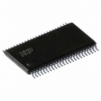
PCF8562TT/2,118 NXP Semiconductors, PCF8562TT/2,118 Datasheet - Page 24

PCF8562TT/2,118
Manufacturer Part Number
PCF8562TT/2,118
Description
IC LCD DRIVER 32/128SEG 48-TSSOP
Manufacturer
NXP Semiconductors
Datasheet
1.PCF8562TT2118.pdf
(37 pages)
Specifications of PCF8562TT/2,118
Package / Case
48-TSSOP
Display Type
LCD
Configuration
7 Segment + DP, 14 Segment (32 Segment)
Interface
I²C
Current - Supply
32µA
Voltage - Supply
1.8 V ~ 5.5 V
Operating Temperature
-40°C ~ 85°C
Mounting Type
Surface Mount
Number Of Digits
16
Number Of Segments
32
Maximum Clock Frequency
2640 Hz
Operating Supply Voltage
1.8 V to 5.5 V
Maximum Power Dissipation
400 mW
Maximum Operating Temperature
+ 85 C
Attached Touch Screen
No
Maximum Supply Current
20 uA
Minimum Operating Temperature
- 40 C
Lead Free Status / RoHS Status
Lead free / RoHS Compliant
For Use With
OM6292 - DEMO BOARD PCA2125 RTCOM10088 - KIT FOR LCD DEMO LPC900622-1003 - KIT FOR LCD DEMO
Digits Or Characters
-
Lead Free Status / Rohs Status
Lead free / RoHS Compliant
Other names
568-2029-2
PCF8562TT/2,518
PCF8562TT/2-T
PCF8562TT/2,518
PCF8562TT/2-T
NXP Semiconductors
PCF8562_5
Product data sheet
7.18 Display controller
7.19 Multiple chip operation
Table 12.
[1]
Table 13.
[1]
[2]
The display controller executes the commands identified by the command decoder. It
contains the device’s status registers and coordinates their effects. The display controller
is also responsible for loading display data into the display RAM in the correct filling order.
For large display configurations or for more segments (> 128 elements) to drive please
refer to the PCF8576D device.
The contact resistance between the SYNC input/output on each cascaded device must be
controlled. If the resistance is too high, the device will not be able to synchronize properly;
this is particularly applicable to chip-on-glass applications. The maximum SYNC contact
resistance allowed for the number of devices in cascade is given in
Bit
7
6 to 2
1
0
Bit
7
6 to 3
2
1 to 0
The bank-select command has no effect in 1:3 and 1:4 multiplex drive modes.
Normal blinking is assumed when the LCD multiplex drive modes 1:3 or 1:4 are selected.
Alternate RAM bank blinking does not apply in 1:3 and 1:4 multiplex drive modes.
Symbol
C
-
I
O
Symbol
C
-
A
BF[1:0]
Bank-select command bits description
Blink-select command bits description
All information provided in this document is subject to legal disclaimers.
0, 1
11110
0, 1
1110
Value
0
1
0
1
Value
0
1
00
01
10
11
Rev. 05 — 19 May 2010
Description
Static
see
fixed value
input bank selection; storage of arriving display data
output bank selection; retrieval of LCD display data
Description
see
fixed value
blink mode selection
blink frequency selection
RAM bit 0
RAM bit 2
RAM bit 0
RAM bit 2
normal blinking
alternate RAM bank blinking
off
1
2
3
Table 8
Table 8
Universal LCD driver for low multiplex rates
[1]
[2]
1:2 multiplex
RAM bits 0 and 1
RAM bits 2 and 3
RAM bits 0 and 1
RAM bits 2 and 3
Table
PCF8562
© NXP B.V. 2010. All rights reserved.
14.
[1]
24 of 37


