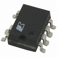
TOP234GN Power Integrations, TOP234GN Datasheet - Page 30

TOP234GN
Manufacturer Part Number
TOP234GN
Description
IC OFFLINE SWIT OVP UVLO 8SMD
Manufacturer
Power Integrations
Series
TOPSwitch®-FXr
Type
Off Line Switcherr
Datasheet
1.TOP234YN.pdf
(36 pages)
Specifications of TOP234GN
Output Isolation
Isolated
Frequency Range
66 ~ 132kHz
Voltage - Output
700V
Power (watts)
30W
Operating Temperature
-40°C ~ 150°C
Package / Case
8-SMD Gull Wing, 7 Leads
Output Voltage
12 V
Input / Supply Voltage (max)
265 VAC
Input / Supply Voltage (min)
85 VAC
Duty Cycle (max)
78 %
Switching Frequency
132 KHz
Supply Current
1.5 mA
Operating Temperature Range
- 40 C to + 150 C
Mounting Style
SMD/SMT
Lead Free Status / RoHS Status
Lead free / RoHS Compliant
Available stocks
Company
Part Number
Manufacturer
Quantity
Price
Company:
Part Number:
TOP234GN
Manufacturer:
PowerInt
Quantity:
350
Part Number:
TOP234GN
Manufacturer:
POWER
Quantity:
20 000
Part Number:
TOP234GN-TL
Manufacturer:
POWER
Quantity:
20 000
The following precautions should be followed when testing
TOPSwitch-FX by itself outside of a power supply. The schematic
shown in Figure 34 is suggested for laboratory testing of
TOPSwitch-FX.
When the DRAIN pin supply is turned on, the part will be in the
auto-restart mode. The CONTROL pin voltage will be oscillating
at a low frequency between 4.8 and 5.8 V and the drain is turned
on every eighth cycle of the CONTROL pin oscillation. If the
CONTROL pin power supply is turned on while in this auto-
Typical Performance Characteristics
30
TOP232-234
BENCH TEST PRECAUTIONS FOR EVALUATION OF ELECTRICAL CHARACTERISTICS
B
7/01
1.0
.9
.8
.7
.6
.5
.4
.3
-250
1.1
1.0
.9
.8
.7
.6
.5
.4
.3
Scaling Factors:
0
TOP234 1.50
TOP233 1.00
TOP232 0.50
Maximum and minimum levels
are based on characterization.
Minimum
CURRENT LIMIT vs. MULTI-FUNCTION
5K
-200
CURRENT LIMIT vs. EXTERNAL
External Current Limit Resistor R
CURRENT LIMIT RESISTANCE
Typical
10K
PIN CURRENT
-150
I
M
(µA)
Maximum
15K
restart mode, there is only a 12.5% chance that the CONTROL
pin oscillation will be in the correct state (drain active state) so
that the continuous drain voltage waveform may be observed.
It is recommended that the V
and the DRAIN pin power supply second if continuous drain
voltage waveforms are to be observed. The 12.5% chance of
being in the correct state is due to the divide-by-8 counter.
Temporarily shorting the CONTROL pin to the SOURCE pin
will reset TOPSwitch-FX, which then will come up in the
correct state.
-100
20K
IL
(Ω)
-50
Scaling Factors:
TOP234 1.50
TOP233 1.00
TOP232 0.50
25K
PI-2539-033001
PI-2540-033001
C
power supply be turned on first
30K
0
200
180
160
140
120
100
80
60
200
180
160
140
120
100
80
60


