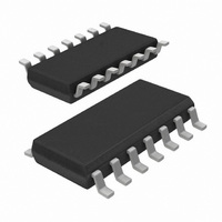
TEA1520T/N2,518 NXP Semiconductors, TEA1520T/N2,518 Datasheet - Page 7

TEA1520T/N2,518
Manufacturer Part Number
TEA1520T/N2,518
Description
IC CTRLR SMPS OVP OTP HV 14SOIC
Manufacturer
NXP Semiconductors
Series
STARplug™r
Specifications of TEA1520T/N2,518
Output Isolation
Isolated
Frequency Range
10 ~ 200kHz
Voltage - Input
7.5 ~ 40 V
Voltage - Output
650V
Power (watts)
1W
Operating Temperature
-40°C ~ 145°C
Package / Case
14-SOIC (0.154", 3.90mm Width)
Output Voltage
650 V
Output Current
125 uA
Mounting Style
SMD/SMT
For Use With
568-4326 - KIT DEMO STARPLUG BRONCO II
Lead Free Status / RoHS Status
Lead free / RoHS Compliant
Other names
568-2333-2
935269963518
TEA1520TD-T
935269963518
TEA1520TD-T
Philips Semiconductors
TEA152X_FAM_2
Product data sheet
8.5 Demagnetization
8.6 Minimum and maximum duty factor
8.7 Overcurrent protection
8.8 Short-circuit winding protection
Figure 5
the output voltage V
the factor N (determined by the turns ratio of the transformer).
system switches exactly at minimum drain voltage for ringing frequencies of 480 kHz, thus
reducing the switch-on losses to a minimum. At 200 kHz, the next primary stroke is
started at 33 before the valley. The switch-on losses are still reduced significantly.
The system operates in discontinuous conduction mode all the time. As long as the
secondary stroke has not ended, the oscillator will not start a new primary stroke. During
the first t
be necessary in applications where the transformer has a large leakage inductance and at
low output voltages.
The minimum duty factor of the switched mode power supply is 0 %. The maximum duty
factor is set to 75 % (typical value at 100 kHz oscillation frequency).
The cycle-by-cycle peak drain current limit circuit uses the external source resistor R
measure the current. The circuit is activated after the leading edge blanking time t
protection circuit limits the source voltage to V
current.
The short-circuit winding protection circuit is also activated after the leading edge blanking
time. If the source voltage exceeds the short-circuit winding protection voltage V
stops switching. Only a power-on reset will restart normal operation. The short-circuit
winding protection also protects in case of a secondary diode short circuit.
Fig 5. Typical phase of drain ringing at switch-on (at N
suppr
shows a typical curve for a reflected output voltage N
seconds, demagnetization recognition is suppressed. This suppression may
o
phase
(see
( )
Rev. 02 — 25 January 2006
40
20
20
40
0
0
Figure
6) transferred to the primary side of the transformer with
200
400
source(max)
600
SMPS ICs for low-power systems
, and thus limits the primary peak
f (kHz)
TEA152x family
V
mgt424
© Koninklijke Philips Electronics N.V. 2006. All rights reserved.
o
= 80 V)
800
Figure 5
V
o
of 80 V. This voltage is
shows that the
swp
leb
, the IC
. The
7 of 20
I
to


