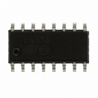
L6591 STMicroelectronics, L6591 Datasheet - Page 29

L6591
Manufacturer Part Number
L6591
Description
IC CTRLR PWM PROG CM HV 16SOIC
Manufacturer
STMicroelectronics
Specifications of L6591
Output Isolation
Isolated
Frequency Range
168 ~ 192kHz
Voltage - Input
8.7 ~ 22 V
Power (watts)
750mW
Operating Temperature
-40°C ~ 150°C
Package / Case
16-SOIC (0.154", 3.90mm Width)
Output Voltage
5 V
Input Voltage
25 V
Operating Temperature Range
- 40 C to + 150 C
Mounting Style
SMD/SMT
Duty Cycle (max)
50 %
For Use With
497-8335 - BOARD EVAL FOR L6591
Lead Free Status / RoHS Status
Lead free / RoHS Compliant
Other names
497-8286
Available stocks
Company
Part Number
Manufacturer
Quantity
Price
Part Number:
L6591
Manufacturer:
ST
Quantity:
20 000
Part Number:
L6591TR
Manufacturer:
ST
Quantity:
20 000
L6591
Equation 3
During the negative-going ramp of the sawtooth a clock pulse is released. A T flip-flop, along
with a logic circuit, separates the odd and the even clock pulses. The even ones turn off the
low-side MOSFET first and, after a dead time T
the high-side MOSFET is turned off (and the low-side MOSFET turned on after the dead
time T
comparator to do the job or, in case of open control loop, the odd clock pulses will limit the
maximum ON-time within one oscillator cycle. In this way, the maximum duty cycle will be
limited right below 50% and the operating frequency of the converter will be half that of the
oscillator. Precisely, with reference to the waveforms in
maximum achievable duty cycle is:
Equation 4
At start-up the first clock pulse will turn on the low-side MOSFET for 10 oscillator cycles to
charge the bootstrap capacitor and then the high-side MOSFET will switch on. When the IC
resumes switching during burst-mode operation the first clock pulse will turn-on the low-side
MOSFET first to charge the bootstrap capacitor, and just after the second clock pulse the
high-side MOSFET will switch-on. In this way the bootstrap capacitor will always be charged
and ready to supply the high-side floating driver. The oscillator waveforms are illustrated in
Figure 50
The dead-time T
plus an internal delay of 125 ns; hence it depends on the timing capacitor C
resistor R
Equation 5
There is an internal 325 ns limit to the minimum T
condition of shoot-through can be generated, however it is recommended not to use
capacitor values lower than 220 pF.
d
) in response to the control loop; in case of overload it will be the overcurrent
T
as well.
and is given by the approximate relationship:
d
equals the duration of the negative-going ramp of the oscillator sawtooth
D
max
T
d
=
=
Doc ID 14821 Rev 5
T
C
SW
2
T
T
SW
f
osc
. 2
−
T
54
≈
d
⋅
(
=
10
C
0
2
T
−
5 .
1 .
R (
3
−
−
. 1
T
d
T
. 3
39
, turn on the high-side MOSFET. Normally,
+
R
T
SW
d
d
05
1150
T
value, to make sure that no hazardous
=
+
0
125
Figure 50
))
5 .
(
1
⋅
10
−
T
−
d
9
, where T
f
osc
Application information
)
sw
T
= 2/f
and the
osc
, the
29/41


