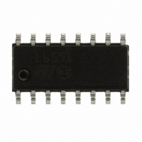
L6591 STMicroelectronics, L6591 Datasheet - Page 26

L6591
Manufacturer Part Number
L6591
Description
IC CTRLR PWM PROG CM HV 16SOIC
Manufacturer
STMicroelectronics
Specifications of L6591
Output Isolation
Isolated
Frequency Range
168 ~ 192kHz
Voltage - Input
8.7 ~ 22 V
Power (watts)
750mW
Operating Temperature
-40°C ~ 150°C
Package / Case
16-SOIC (0.154", 3.90mm Width)
Output Voltage
5 V
Input Voltage
25 V
Operating Temperature Range
- 40 C to + 150 C
Mounting Style
SMD/SMT
Duty Cycle (max)
50 %
For Use With
497-8335 - BOARD EVAL FOR L6591
Lead Free Status / RoHS Status
Lead free / RoHS Compliant
Other names
497-8286
Available stocks
Company
Part Number
Manufacturer
Quantity
Price
Part Number:
L6591
Manufacturer:
ST
Quantity:
20 000
Part Number:
L6591TR
Manufacturer:
ST
Quantity:
20 000
Application information
6.3
6.4
26/41
Figure 45. How the L6591 can switch off a PFC controller at light load
PWM control block
The device is specific for secondary feedback. Typically, there is a TL431 at the secondary
side and an optocoupler that transfers output voltage information to the PWM control at the
primary side, crossing the isolation barrier. The PWM control input (pin #7, COMP) is driven
directly by the phototransistor’s collector (the emitter is grounded) to modulate the duty
cycle. It is recommended to place a small filter capacitor between the pin and GND (#11), as
close to the IC as possible to reduce switching noise pick up, to set a pole in the output-to-
control transfer function.
PWM comparator, PWM latch and hiccup-mode OCP
The PWM comparator senses the voltage across the current sense resistor (Rs) and, by
comparing it with the programming signal derived by the voltage on pin COMP (#7),
determines the exact time when the high-side MOSFET is to be switched off. The PWM
latch avoids spurious switching, which might be caused by the noise generated (“double-
pulse suppression”).
A second comparator senses the voltage on the current sense input and shuts the IC down
if the voltage at the pin exceeds 1.5 V. Such an anomalous condition is typically generated
by either a short circuit of one of the secondary rectifiers or a shorted secondary winding or
a saturated transformer. This condition is latched as long as the IC is supplied; hence if the
IC is supplied by an external source it is necessary to disconnect the source to restart the
IC.
To distinguish an actual malfunction from a disturbance (e.g. induced during ESD tests), the
first time the comparator is tripped the protection circuit enters a “warning state”. If in the
next switching cycle the comparator is not tripped, a temporary disturbance is assumed and
the protection logic will be reset in its idle state; if the comparator will be tripped again a real
malfunction is assumed and the L6591 will be stopped.
If the device is self-supplied no energy is coming from the self-supply circuit, then the
voltage on the Vcc capacitor will decay and cross the UVLO threshold after some time,
which clears the latch. The internal start-up generator is still off, then the Vcc voltage still
needs to go below its restart voltage before the Vcc capacitor is charged again and the IC
restarted. Ultimately, either of the above mentioned failures will result in a low-frequency
intermittent operation (Hiccup-mode operation), with very low stress on the power circuit.
The timing diagram of
L6591
L6591
Vref
Vref
6
6
8
8
PFC_STOP
PFC_STOP
Figure 46
47 k
47 kΩ
B C547
B C547
5.6 k
5.6 kΩ
Doc ID 14821 Rev 5
illustrates this operation.
B C547
B C547
ZCD
ZCD
L6562
L6562
L6591
L6591
L6563
L6563
8
8
PFC_OK
PFC_OK
(AC_OK)
(AC_OK)
PFC_STOP
PFC_STOP
L6591


