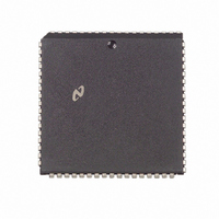
DP8421AV-25 National Semiconductor, DP8421AV-25 Datasheet - Page 35

DP8421AV-25
Manufacturer Part Number
DP8421AV-25
Description
IC CTRLR/DVR CMOS PROGRAM 68PLCC
Manufacturer
National Semiconductor
Datasheet
1.DP8420AV-25.pdf
(58 pages)
Specifications of DP8421AV-25
Controller Type
Dynamic RAM (DRAM)
Voltage - Supply
4.5 V ~ 5.5 V
Operating Temperature
0°C ~ 70°C
Package / Case
68-PLCC
Lead Free Status / RoHS Status
Contains lead / RoHS non-compliant
Other names
*DP8421AV-25
Available stocks
Company
Part Number
Manufacturer
Quantity
Price
Company:
Part Number:
DP8421AV-25
Manufacturer:
Texas Instruments
Quantity:
10 000
Part Number:
DP8421AV-25
Manufacturer:
NS/国半
Quantity:
20 000
7 0 RAS and CAS Configuration Modes
7 5 PAGE BURST MODE
In a static column page or burst mode system the least
significant bits must be tied to the column address in order
to ensure that the page burst accesses are to sequential
memory addresses as shown in Figure 30
mode system the least significant bits must be tied to the
highest column and row address bits in order to ensure that
sequential address bits are the ‘‘nibble’’ bits for nibble mode
accesses (Figure 30) The ECAS inputs may then be tog-
See table below for row column
Assume that the least significant address bits are used for byte addressing Given a 32-bit system A0 A1 would be
used for byte addressing
X
Nibble mode values for R and C assume a system using 1 Mbit DRAMs
Addresses
e
Address
Address
Column
Row
DON’T CARE the user can do as he pleases
B0
B1
bank address bit map A0 A1 are used for byte addressing in this example
C9 R9
Nibble Mode
C0– 8
FIGURE 30 Page Static Column Nibble Mode System
A4
A5
e
X
e
A2 A3
X
256 Bits Page
C0– 7
C8–10
In a nibble
A10
A11
e
X
A2–9
e
X
Page Mode Static Column Mode Page Size
C0–8
512 Bits Page
35
C9 10
(Continued)
A11
A12
e
gled with the DP8420A 21A 22A’s address latches in fall-
through mode while AREQ is asserted The ECAS inputs
can also be used to select individual bytes When using nib-
ble mode DRAMS the third and fourth address bits can be
tied to the bank select inputs to perform memory interleav-
ing In page or static column modes the two address bits
after the page size can be tied to the bank select inputs to
select a new bank if the page size is exceeded
X
A2–10
e
X
1024 Bits Page
C0–9
C10
A12
A13
e
X
e
A2–11
X
C0–10
2048 Bits Page
A13
A14
e
X
A2–12
TL F 8588 – D8


