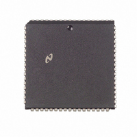
DP8421AV-25 National Semiconductor, DP8421AV-25 Datasheet - Page 29

DP8421AV-25
Manufacturer Part Number
DP8421AV-25
Description
IC CTRLR/DVR CMOS PROGRAM 68PLCC
Manufacturer
National Semiconductor
Datasheet
1.DP8420AV-25.pdf
(58 pages)
Specifications of DP8421AV-25
Controller Type
Dynamic RAM (DRAM)
Voltage - Supply
4.5 V ~ 5.5 V
Operating Temperature
0°C ~ 70°C
Package / Case
68-PLCC
Lead Free Status / RoHS Status
Contains lead / RoHS non-compliant
Other names
*DP8421AV-25
Available stocks
Company
Part Number
Manufacturer
Quantity
Price
Company:
Part Number:
DP8421AV-25
Manufacturer:
Texas Instruments
Quantity:
10 000
Part Number:
DP8421AV-25
Manufacturer:
NS/国半
Quantity:
20 000
6 0 Port A Wait State Support
6 2 DTACK TYPE OUTPUT
With the R7 address bit asserted during programming the
user selects the DTACK type output As long as DTACK is
sampled negated by the CPU wait states are inserted into
the current access cycle as shown in Figure 23 Once
DTACK is sampled asserted the access cycle is completed
by the CPU DTACK which is normally negated is pro-
grammed to assert a number of positive edges and or neg-
ative levels from the event that starts RAS for the access
DTACK can also be programmed to function during page
burst mode accesses Once DTACK is asserted and the
ECAS inputs are negated with AREQ asserted DTACK can
be programmed to negate and assert from the ECAS inputs
toggling to perform a page burst mode operation Once
AREQ is negated ending the access DTACK will be negat-
ed and stays negated until the next chip selected access
For more details about DTACK type output see Application
Note AN-773
FIGURE 24a WAITIN Example (DTACK is Sampled at the ‘‘T3’’ Falling Clock Edge)
FIGURE 23 DTACK Type Output
(Continued)
29
6 3 DYNAMICALLY INCREASING THE
NUMBER OF WAIT STATES
The user can increase the number of positive edges of CLK
before DTACK is asserted or WAIT is negated With the
input WAITIN asserted the user can delay DTACK asserting
or WAIT negating either one or two more positive edges of
CLK The number of edges is programmed through address
bit R6 If the user is increasing the number of positive edges
in a delay that contains a negative level the positive edges
will be met before the negative level For example if the user
programmed DTACK of
grammed as 2T would increase the number of positive edg-
es resulting in DTACK of 2 T as shown in Figure 24a Simi-
larly WAITIN can increase the number of positive edges in
a page burst access WAITIN can be permanently asserted
in systems requiring an increased number of wait states
WAITIN can also be asserted and negated depending on
the type of access As an example a user could invert the
WRITE line from the CPU and connect the output to
WAITIN This could be used to perform write accesses with
1 wait state and read accesses with 2 wait states as shown
in Figure 24b
T
asserting WAITIN
TL F 8588 – C1
TL F 8588 – 97
pro-


