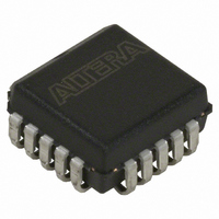
EPC1213LC20 Altera, EPC1213LC20 Datasheet - Page 49

EPC1213LC20
Manufacturer Part Number
EPC1213LC20
Description
IC CONFIG DEVICE 212KBIT 20-PLCC
Manufacturer
Altera
Series
EPCr
Datasheet
1.EPC4QI100N.pdf
(116 pages)
Specifications of EPC1213LC20
Programmable Type
OTP
Memory Size
212kb
Voltage - Supply
4.75 V ~ 5.25 V
Operating Temperature
0°C ~ 70°C
Package / Case
20-PLCC
For Use With
PLMJ1213 - PROGRAMMER ADAPTER 20 PIN J-LEAD
Lead Free Status / RoHS Status
Contains lead / RoHS non-compliant
Other names
544-2188-5
Available stocks
Company
Part Number
Manufacturer
Quantity
Price
Company:
Part Number:
EPC1213LC20
Manufacturer:
AT
Quantity:
23
Company:
Part Number:
EPC1213LC20
Manufacturer:
ALTERA
Quantity:
5 510
Company:
Part Number:
EPC1213LC20
Manufacturer:
TI
Quantity:
5 510
Part Number:
EPC1213LC20
Manufacturer:
ALTERA/阿尔特拉
Quantity:
20 000
Chapter 2: Altera Enhanced Configuration Devices
Data Compression
Data Compression
© December 2009 Altera Corporation
1
You can use the .hexout to program blank enhanced configuration devices, update
portions of the flash memory (for example, a new configuration page), or both. This
file uses the Intel hexadecimal file format and contains 16 Mbits or 2 Mbytes of data.
Table 2–2
Table 2–2. File Format (.map)
To perform partial flash memory updates, select the relevant portions of the .hexout
using memory map information provided in the .map file.
Configuration data and processor space data could exist within the same physical
data block. In such cases, erasing the physical data block would affect both
configuration and processor data, requiring you to update both. You can avoid this
situation by storing application data starting from the next available whole data
block.
Enhanced configuration devices support an efficient compression algorithm that
compresses configuration data by 1.9× for typical designs, effectively doubling the
size of the device. To select the right density for enhanced configuration devices, you
should pre-calculate the total size of uncompressed configuration space.
By clicking Options (Convert Programming Files window), you can turn on the
Compression mode option in the Programming Object File Options window with pof
selected as the programming file type, as shown in
Figure 2–12. Selecting Compression Mode
Note to
(1) All the addresses in this file are byte addresses.
Table
BOTTOM BOOT
OPTION BITS
lists the format of the .map file.
PAGE 0
2–2:
MAIN
Block
(Note 1)
0x00000000
0x00010000
0x00010040
0x001FFFE0
Start Address
Configuration Handbook (Complete Two-Volume Set)
Figure
2–12.
0x0000001F
0x0001003F
0x0001AD7F
0x001FFFFF
End Address
2–13


