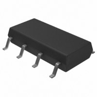
S-24CS04AFJ-TB-G Seiko Instruments, S-24CS04AFJ-TB-G Datasheet - Page 10

S-24CS04AFJ-TB-G
Manufacturer Part Number
S-24CS04AFJ-TB-G
Description
IC EEPROM 4KBIT 400KHZ 8SOP
Manufacturer
Seiko Instruments
Datasheet
1.S-24CS01AFT-TB-G.pdf
(47 pages)
Specifications of S-24CS04AFJ-TB-G
Format - Memory
EEPROMs - Serial
Memory Type
EEPROM
Memory Size
4K (512 x 8)
Speed
400kHz
Interface
I²C, 2-Wire Serial
Voltage - Supply
1.8 V ~ 5.5 V
Operating Temperature
-40°C ~ 85°C
Package / Case
8-SOP
Organization
512 x 8
Interface Type
2-Wire
Maximum Clock Frequency
0.4 MHz
Supply Voltage (max)
5.5 V
Supply Voltage (min)
1.8 V
Maximum Operating Current
4 mA
Maximum Operating Temperature
+ 85 C
Mounting Style
SMD/SMT
Minimum Operating Temperature
- 40 C
Operating Supply Voltage
5.5 V
Lead Free Status / RoHS Status
Lead free / RoHS Compliant
Available stocks
Company
Part Number
Manufacturer
Quantity
Price
Part Number:
S-24CS04AFJ-TB-G
Manufacturer:
SEK
Quantity:
20 000
10
2-WIRE CMOS SERIAL E
S-24CS01A/02A/04A/08A
1. Start Condition
2. Stop Condition
Operation
Start is identified by a high to low transition of the SDA line while the SCL line is stable at high.
Every operation begins from a start condition.
Stop is identified by a low to high transition of the SDA line while the SCL line is stable at high.
When a device receives a stop condition during a read sequence, the read operation is interrupted, and
the device enters standby mode.
When a device receives a stop condition during a write sequence, the reception of the write data is halted,
and the E
2
PROM initiates a write cycle.
SCL
SDA
2
PROM
t
SU.STA
Start Condition
Figure 9 Start / Stop Conditions
t
HD.STA
Seiko Instruments Inc.
t
SU.STO
Stop Condition
Rev.4.5
_00


