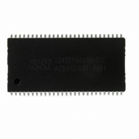
IS42S16400D-7TL ISSI, Integrated Silicon Solution Inc, IS42S16400D-7TL Datasheet - Page 18

IS42S16400D-7TL
Manufacturer Part Number
IS42S16400D-7TL
Description
IC SDRAM 64MBIT 143MHZ 54TSOP
Manufacturer
ISSI, Integrated Silicon Solution Inc
Datasheet
1.IS42S16400D-7TL.pdf
(57 pages)
Specifications of IS42S16400D-7TL
Package / Case
54-TSOP II
Memory Size
64M (4M x 16)
Format - Memory
RAM
Memory Type
SDRAM
Speed
143MHz
Interface
Parallel
Voltage - Supply
3 V ~ 3.6 V
Operating Temperature
0°C ~ 70°C
Data Bus Width
16 bit
Organization
1 Mbit x 16
Maximum Clock Frequency
143 MHz
Access Time
7 ns
Supply Voltage (max)
3.6 V
Supply Voltage (min)
3 V
Maximum Operating Current
100 mA
Maximum Operating Temperature
+ 70 C
Minimum Operating Temperature
0 C
Mounting Style
SMD/SMT
Lead Free Status / RoHS Status
Lead free / RoHS Compliant
Lead Free Status / RoHS Status
Lead free / RoHS Compliant, Lead free / RoHS Compliant
Other names
706-1019
Available stocks
Company
Part Number
Manufacturer
Quantity
Price
Company:
Part Number:
IS42S16400D-7TL
Manufacturer:
ISSI
Quantity:
1 000
Company:
Part Number:
IS42S16400D-7TL
Manufacturer:
ISSI
Quantity:
504
Part Number:
IS42S16400D-7TL
Manufacturer:
ISSI
Quantity:
20 000
Part Number:
IS42S16400D-7TLI
Manufacturer:
ISSI
Quantity:
20 000
IS42S16400D
Burst Length
Read and write accesses to the SDRAM are burst ori-
ented, with the burst length being programmable, as
shown in MODE REGISTER DEFINITION. The burst
length determines the maximum number of column loca-
tions that can be accessed for a given READ or WRITE
command. Burst lengths of 1, 2, 4 or 8 locations are
available for both the sequential and the interleaved burst
types, and a full-page burst is available for the sequential
type. The full-page burst is used in conjunction with the
BURST TERMINATE command to generate arbitrary
burst lengths.
Reserved states should not be used, as unknown opera-
tion or incompatibility with future versions may result.
When a READ or WRITE command is issued, a block of
columns equal to the burst length is effectively selected.
18
BURST DEFINITION
Length
Burst
Page
Full
(y)
2
4
8
(location 0-y)
n = A0-A7
A2
0
0
0
0
1
1
1
1
Starting Column
Address
A1
A1
0
0
1
1
0
0
1
0
0
1
1
1
A0
A0
A0
0
1
0
1
0
1
0
1
1
0
1
0
1
0
Type = Sequential
Cn, Cn + 1, Cn + 2
Cn + 3, Cn + 4...
0-1-2-3-4-5-6-7
1-2-3-4-5-6-7-0
2-3-4-5-6-7-0-1
3-4-5-6-7-0-1-2
4-5-6-7-0-1-2-3
5-6-7-0-1-2-3-4
6-7-0-1-2-3-4-5
7-0-1-2-3-4-5-6
…Cn - 1,
0-1-2-3
1-2-3-0
2-3-0-1
3-0-1-2
Cn…
0-1
1-0
All accesses for that burst take place within this block,
meaning that the burst will wrap within the block if a
boundary is reached. The block is uniquely selected by
A1-A7 (x16) when the burst length is set to two; by A2-A7
(x16) when the burst length is set to four; and by A3-A7
(x16) when the burst length is set to eight. The remaining
(least significant) address bit(s) is (are) used to select the
starting location within the block. Full-page bursts wrap
within the page if the boundary is reached.
Burst Type
Accesses within a given burst may be programmed to be
either sequential or interleaved; this is referred to as the
burst type and is selected via bit M3.
The ordering of accesses within a burst is determined by
the burst length, the burst type and the starting column
address, as shown in BURST DEFINITION table.
Order of Accesses Within a Burst
Integrated Silicon Solution, Inc. — www.issi.com
Type = Interleaved
0-1-2-3-4-5-6-7
1-0-3-2-5-4-7-6
2-3-0-1-6-7-4-5
3-2-1-0-7-6-5-4
4-5-6-7-0-1-2-3
5-4-7-6-1-0-3-2
6-7-4-5-2-3-0-1
7-6-5-4-3-2-1-0
Not Supported
0-1-2-3
1-0-3-2
2-3-0-1
3-2-1-0
0-1
1-0
11/21/07
Rev. E


