AT93C46D-TH-B Atmel, AT93C46D-TH-B Datasheet
AT93C46D-TH-B
Specifications of AT93C46D-TH-B
Available stocks


Related parts for AT93C46D-TH-B


AT93C46D-TH-B Summary of contents
Page 1
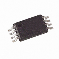
... PDIP, 8-lead JEDEC SOIC, 8-lead Ultra Thin mini- MAP (MLP 2x3), 8-lead TSSOP, and 8-lead dBGA2 packages. The AT93C46D is enabled through the Chip Select pin (CS) and accessed via a three-wire serial interface consisting of Data Input (DI), Data Output (DO), and Shift Clock (SK) ...
Page 2
... If the ORG pin is left unconnected and the application does not load the input beyond the capability of the internal 1 Meg ohm pullup, then the “x 16” organization is selected. 2. For the AT93C46D, if the “x 16” organization is the mode of choice and pin 6 (ORG) is left ® unconnected, Atmel recommends using AT93C46E device ...
Page 3
... 2 2.7V ≤ V ≤ 5.5V CC − 0 0. 1.8V ≤ V ≤ 2.7V CC − 100 µA OH AT93C46D = +1.8V (unless otherwise noted) CC Max Units +1.8V to +5.5V (unless otherwise noted) CC Min Typ Max 1.8 5.5 2.7 5.5 4.5 5.5 0.5 2.0 0.5 2.0 0.4 1 ...
Page 4
... Output Delay to “0” PD0 Status Valid High t DF Impedance t Write Cycle Time WP (1) Endurance 5.0V, 25°C Note: 1. This parameter is ensured by characterization. AT93C46D 4 = −40° 85° Test Condition 4.5V ≤ V ≤ 5.5V CC 2.7V ≤ V ≤ 5.5V CC 1.8V ≤ V ≤ 5.5V CC 4.5V ≤ V ≤ 5.5V CC 2.7V ≤ ...
Page 5
... The Xs in the address field represent DON’T CARE values and must be clocked. 2. Functional Description The AT93C46D is accessed via a simple and versatile three-wire serial communication inter- face. Device operation is controlled by seven instructions issued by the host processor. A valid instruction starts with a rising edge of CS and consists of a start bit (logic “1”) followed by the appropriate op code and the desired memory address location ...
Page 6
... ERASE/WRITE DISABLE (EWDS): To protect against accidental data disturb, the Erase/Write Disable (EWDS) instruction disables all programming modes and should be executed after all programming operations. The operation of the Read instruction is independent of both the EWEN and EWDS instructions and can be executed at any time. AT93C46D 6 = 5.0V ± 10 5.0V ± ...
Page 7
... Timing Diagrams Figure 3-1. Synchronous Data Timing Note: 1. This is the minimum SK period. Table 3-1. Figure 3-2. READ Timing High Impedance 5193F–SEEPR–1/08 μs Organization Key for Timing Diagrams AT93C46D (1K) I AT93C46D ...
Page 8
... Figure 3-3. EWEN Timing Figure 3-4. EWDS Timing Figure 3-5. WRITE Timing HIGH IMPEDANCE DO AT93C46D 8 ... ... ... ... BUSY READY t WP 5193F–SEEPR–1/08 ...
Page 9
... Figure 3-6. WRAL Timing HIGH IMPEDANCE DO Note: 1. Valid only 4.5V to 5.5V. CC Figure 3-7. ERASE Timing HIGH IMPEDANCE DO 5193F–SEEPR–1/ ... ... N-1 N-2 AT93C46D ... D0 N BUSY READY STANDBY CHECK STATUS HIGH IMPEDANCE BUSY READY ...
Page 10
... Figure 3-8. ERAL Timing HIGH IMPEDANCE DO Note: 1. Valid only 4.5V to 5.5V. CC AT93C46D STANDBY CHECK STATUS BUSY HIGH IMPEDANCE READY t WP 5193F–SEEPR–1/08 ...
Page 11
... AT93C46D Ordering Information Ordering Code AT93C46D-PU (Bulk form only) (1) AT93C46DN-SH-B (NiPdAu Lead finish) (2) AT93C46DN-SH-T (NiPdAu Lead finish) (1) AT93C46D-TH-B (NiPdAu Lead finish) (2) AT93C46D-TH-T (NiPdAu Lead finish) (2) AT93C46DY6-YH-T (NiPdAu Lead finish) (2) AT93C46DU3-UU-T (3) AT93C46D-W-11 Notes: 1. “-B” denotes bulk 2. “-T” denotes tape and reel. SOIC = 4K per reel. TSSOP, Ultra Thin Mini MAP, and dBGA2 = 5K per reel. ...
Page 12
... Part Marking Scheme 5.1 AT93C46D 8-PDIP TOP MARK Seal Year | | |---|---|---|---|---|---|---|---| |---|---|---|---|---|---|---|---| |---|---|---|---|---|---|---|---| * Lot Number |---|---|---|---|---|---|---|---| | Pin 1 Indicator (Dot) 5.2 AT93C46D 8-SOIC TOP MARK |---|---|---|---|---|---|---|---| |---|---|---|---|---|---|---|---| |---|---|---|---|---|---|---|---| * Lot Number |---|---|---|---|---|---|---|---| | Pin 1 Indicator (Dot) AT93C46D SEAL YEAR Seal Week 6: 2006 | | 7: 2007 8: 2008 2009 Lot Number to Use ALL Characters in Marking BOTTOM MARK ...
Page 13
... |---|---|---|---|---| |---|---|---|---|---| BOTTOM MARK |---|---|---|---|---|---|---| |---|---|---|---|---|---|---| |---|---|---|---|---|---|---| <- Pin 1 Indicator 5.4 AT93C46D 8-Ultra Thin Mini MAP TOP MARK |---|---|---| |---|---|---| H 1 |---|---|---| |---|---|---| * | Pin 1 Indicator (Dot) 5193F–SEEPR–1/ SEAL YEAR 6: 2006 7: 2007 W 8: 2008 9: 2009 Y = YEAR OF ASSEMBLY XX = ATMEL LOT NUMBER TO COORESPOND WITH NSEB TRACE CODE LOG BOOK. ...
Page 14
... AT93C46D dBGA2 TOP MARK LINE 1-------> LINE 2-------> ONE DIGIT YEAR CODE 4: 2004 5: 2005 6: 2006 M = SEAL MONTH (USE ALPHA DESIGNATOR A- JANUARY B = FEBRUARY " " """"""" OCTOBER K = NOVEMBER L = DECEMBER TC = TRACE CODE (ATMEL LOT NUMBERS TO CORRESPOND ...
Page 15
... Dambar protrusions. Dambar protrusions shall not exceed 0.010 (0.25 mm). 2325 Orchard Parkway San Jose, CA 95131 R 5193F–SEEPR–1/ TITLE 8P3, 8-lead, 0.300" Wide Body, Plastic Dual In-line Package (PDIP) AT93C46D End View COMMON DIMENSIONS (Unit of Measure = inches) MIN NOM MAX SYMBOL A 0.210 A2 0.115 0.130 ...
Page 16
... JEDEC SOIC TOP VIEW e e SIDE VIEW Note: These drawings are for general information only. Refer to JEDEC Drawing MS-012, Variation AA for proper dimensions, tolerances, datums, etc. 1150 E. Cheyenne Mtn. Blvd. Colorado Springs, CO 80906 R AT93C46D TITLE 8S1, 8-lead (0.150" Wide Body), Plastic Gull Wing ...
Page 17
... Dimension D and determined at Datum Plane H. 2325 Orchard Parkway San Jose, CA 95131 R 5193F–SEEPR–1/ TITLE 8A2, 8-lead, 4.4 mm Body, Plastic Thin Shrink Small Outline Package (TSSOP) AT93C46D L1 L End View COMMON DIMENSIONS (Unit of Measure = mm) MIN MAX SYMBOL NOM D 2.90 3.00 3 ...
Page 18
... Bottem View 8 SOLDER BALLS 1. This drawing is for general information only. 2. Dimension 'b' is measured at maximum solder ball diameter. 1150 E. Cheyenne Mtn. Blvd. Colorado Springs, CO 80906 R AT93C46D TITLE 8U3-1, 8-ball, 1.50 x 2.00 mm Body, 0.50 mm pitch, Small Die Ball Grid Array Package (dBGA2) 1 ...
Page 19
... COMMON DIMENSIONS (Unit of Measure = mm) MIN NOM MAX SYMBOL D 2.00 BSC E 3.00 BSC D2 1.40 1. 0.60 A1 0.0 0.02 0. 0.55 A3 0.20 REF L 0.20 0.30 0.40 e 0.50 BSC b 0.20 0.25 0.30 DRAWING NO. AT93C46D b (8X) (8X) Pin 1 ID Pin (8X) L (8X) NOTE 2 10/16/07 REV. 8Y6 D 19 ...
Page 20
... Revision History Doc. Rev. 5193F 5193E 5193D 5193C 5193C 5193B 5193A AT93C46D 20 Date Comments 1/2008 Removed ‘preliminary’ status 11/2007 Modified ‘max’ value in AC Characteristics table Moved Pinout figure Added new feature for Die Sales 8/2007 Modified Ordering Information table layout ...
Page 21
... Disclaimer: The information in this document is provided in connection with Atmel products. No license, express or implied, by estoppel or otherwise, to any intellectual property right is granted by this document or in connection with the sale of Atmel products. EXCEPT AS SET FORTH IN ATMEL’S TERMS AND CONDI- TIONS OF SALE LOCATED ON ATMEL’S WEB SITE, ATMEL ASSUMES NO LIABILITY WHATSOEVER AND DISCLAIMS ANY EXPRESS, IMPLIED OR STATUTORY WARRANTY RELATING TO ITS PRODUCTS INCLUDING, BUT NOT LIMITED TO, THE IMPLIED WARRANTY OF MERCHANTABILITY, FITNESS FOR A PARTICULAR PURPOSE, OR NON-INFRINGEMENT ...