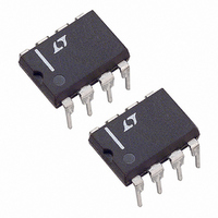
LT1011ACN8#PBF Linear Technology, LT1011ACN8#PBF Datasheet - Page 14

LT1011ACN8#PBF
Manufacturer Part Number
LT1011ACN8#PBF
Description
IC VOLTAGE COMPARATOR 5V 8-DIP
Manufacturer
Linear Technology
Type
General Purposer
Datasheet
1.LT1011CN8PBF.pdf
(16 pages)
Specifications of LT1011ACN8#PBF
Number Of Elements
1
Output Type
Open Collector
Voltage - Supply
3 V ~ 36 V, ±1.5 V ~ 18 V
Mounting Type
Through Hole
Package / Case
8-DIP (0.300", 7.62mm)
Comparator Type
General Purpose
No. Of Comparators
1
Response Time
150ns
Ic Output Type
Open Collector
Supply Current
3.2mA
Supply Voltage Range
3V To ± 18V
Amplifier Case Style
DIP
Rohs Compliant
Yes
Number Of Elements
1
Technology
Bipolar
Input Offset Voltage
750uV
Input Bias Current (typ)
25nA
Single Supply Voltage (typ)
9/12/15/18/24/28V
Dual Supply Voltage (typ)
±3/±5/±9/±12V
Supply Current (max)
4@±15VmA
Power Supply Requirement
Single/Dual
Common Mode Rejection Ratio
115dB
Voltage Gain In Db
113.98dB
Single Supply Voltage (min)
5V
Single Supply Voltage (max)
30V
Dual Supply Voltage (min)
±2.5V
Dual Supply Voltage (max)
±15V
Operating Temp Range
0C to 70C
Operating Temperature Classification
Commercial
Mounting
Through Hole
Pin Count
8
Package Type
PDIP N
Lead Free Status / RoHS Status
Lead free / RoHS Compliant
Available stocks
Company
Part Number
Manufacturer
Quantity
Price
LT1011/LT1011A
SCHEMATIC DIAGRAM
INPUT
INPUT
PACKAGE DESCRIPTION
14
(+)
(–)
2
3
Q31
SEATING
PLANE
Q29
R27
3k
**
*
(0.254 – 1.143)
Q27
0.010 – 0.045*
LEAD DIAMETER IS UNCONTROLLED BETWEEN THE REFERENCE PLANE
AND 0.045" BELOW THE REFERENCE PLANE
FOR SOLDER DIP LEAD FINISH, LEAD DIAMETER IS
D6
Q6
D7
R5
160Ω
D4
Q25
(1.016)
0.040
MAX
Q30
R25
1.6k
OFFSET
D5
Q26
5
(8.509 – 9.398)
(7.747 – 8.509)
0.335 – 0.370
0.305 – 0.335
300Ω
Q28
R4
R26
1.6k
(0.406 – 0.533)
DIA
0.016 – 0.021**
Q5
Q1
R1
1.3k
D1 D2
8-Lead TO-5 Metal Can (.230 Inch PCD)
(1.270)
(0.406 – 0.610)
0.050
MAX
0.016 – 0.024
Q2
R2
1.3k
(Reference LTC DWG # 05-08-1321)
GAUGE
PLANE
Q3
OBSOLETE PACKAGE
Q23
300Ω
R19
500Ω
R6
3.2k
R3
OFFSET/STROBE
(12.700 – 19.050)
Q4
(4.191 – 4.699)
0.165 – 0.185
0.500 – 0.750
R7
3.2k
Q21
6
H Package
Q8
R8
800Ω
R18
275Ω
R23
4k
Q22
REFERENCE
PLANE
Q7
Q10
D3
200Ω
R17
Q9 Q19
R21
960Ω
940Ω
R20
45°TYP
R16
800Ω
R15
700Ω
R14
4.8k
(0.711 – 0.864)
0.028 – 0.034
Q24
Q18
Q17
(2.794 – 4.064)
0.110 – 0.160
INSULATING
Q11
STANDOFF
R9
800Ω
200Ω
R22
Q20
V
4
–
Q16
1011 SD
Q14
R24
400Ω
Q13
PIN 1
(0.686 – 1.143)
0.027 – 0.045
R10
4k
H8 (TO-5) 0.230 PCD 1197
V
8
+
Q12
R11
170Ω
R12
470Ω
(5.842)
0.230
TYP
GND
1
Q15
R13
4Ω
OUTPUT
1011afc
7


