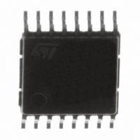
TDA7333013TR STMicroelectronics, TDA7333013TR Datasheet - Page 16

TDA7333013TR
Manufacturer Part Number
TDA7333013TR
Description
IC PROCESSOR RDS/RBDS 16-TSSOP
Manufacturer
STMicroelectronics
Type
RDS/RBDS Signal Processorr
Datasheet
1.TDA7333NTR.pdf
(26 pages)
Specifications of TDA7333013TR
Applications
Radio
Mounting Type
Surface Mount
Package / Case
16-TSSOP
Lead Free Status / RoHS Status
Lead free / RoHS Compliant
Available stocks
Company
Part Number
Manufacturer
Quantity
Price
Functional description
3.7.1
3.7.2
16/26
rds_int register
Figure 9.
rds_qu register
Figure 10. rds_qu register
reset value
bit name
(1)
rds_int
reset value
access
bit name
rds_qu
access
interrupt source i
no interrupt
RDS Block
block A
block B
block D
TA
TAEON
(2)
bit 7 bit 6 bit 5 bit 4 bit 3 bit 2 bit 1 bit 0
rds_int register
write bne ar_res synch itsrc2 itsrc1 itsrc0 int
block name
r/w
bit 7
block C,C’
0
qu3
block A
block B
block D
0
r
bit 6
0
r
qu2
0
r
tsrc2
0
0
0
1
1
1
1
r/w
bit 5
0
qu1
0
r
blk1
0
0
1
1
bit 4
r
qu0
0
0
r
itsrc1
0
0
1
0
0
1
1
r/w
bit 3
blk1
0
0
r
blk0
r/w
0
1
0
1
bit 2
blk0
0
0
r
itsrc0
r/w
0
1
1
0
1
0
1
bit 1
0
0
e
r
bit 0
synz
0
r
0
r
(3) qu[3..0] is a counter of the quality bit information coming
Note : when changing the interrupt mode, one has to
perform a reset of the module (i.e set the bit “ar_res” at
one)
from the RDS demodulator. It is counting the number of bits
which are marked as bad by the demodulator. Only those bits
are allowed to be corrected. Thus the quality bit counter indi-
cates the maximum possible number of bits being corrected.
interrupt bit. It is set to one on every programmed interrupt. It
is reset by reading rds_int register.
interrupt source
itsrc[2:0] select the interrupt source
synchronization information.
1: the module is already synchronized.
0: the module is synchronizing
It is used to force a resynchronization. If it is set to one, the
RDS modules are forced to resynchronization state.
The bit is automatically reset. So it is always read as zero.
RDS block.
if 1, one block has been detected
rds_int and rds_bd_ctrl write order (wh en in SPI mode)
1: rds_int and rds_bd_ctrl are updated with data shifted in.
0: rds_int and rds_bd_ctrl are not updated.
It indicates if the error correction was successfull.
1: the syndrome was zero after the error correction.
0: the syndrome did not become zero and therefore the
correction was not successfull.
1: a block E is detected.This indicates a paging block
which is defined in the RBDS specification used in the
united states of America.
0: an ordinary RDS block A, B, C, c·or D is detected, or no
valid syndrome was found.
bit 0 of block counter (2)
bit 1 of block counter (2)
bit 0 of quality counter (3)
bit 1 of quality counter (3)
bit 2 of quality counter (3)
bit 3 of quality counter (3)
(1)
TDA7333


