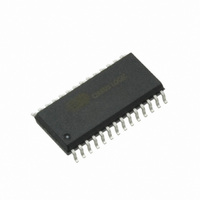
CS8420-DSZ Cirrus Logic Inc, CS8420-DSZ Datasheet - Page 19

CS8420-DSZ
Manufacturer Part Number
CS8420-DSZ
Description
IC CONV S/R DGTL AUDIO 28-SOIC
Manufacturer
Cirrus Logic Inc
Type
Sample Rate Converterr
Datasheet
1.CS8420-CSZ.pdf
(94 pages)
Specifications of CS8420-DSZ
Applications
Digital Audio
Mounting Type
Surface Mount
Package / Case
28-SOIC
Audio Control Type
Sample Rate Converter
Control Interface
3 Wire, Serial
Supply Voltage Range
4.75V To 5.25V
Operating Temperature Range
-40°C To +85°C
Audio Ic Case Style
SOIC
No. Of Pins
28
Lead Free Status / RoHS Status
Lead free / RoHS Compliant
Other names
598-1729
Available stocks
Company
Part Number
Manufacturer
Quantity
Price
Part Number:
CS8420-DSZ
Manufacturer:
CIRRUS
Quantity:
20 000
CS8420
6.
THREE-WIRE SERIAL AUDIO PORTS
A 3-wire serial audio input port and a 3-wire serial audio output port is provided. Each port can be adjusted to suit
the attached device via control registers. The following parameters are adjustable: master or slave, serial clock fre-
quency, audio data resolution, left or right justification of the data relative to left/right clock, optional 1-bit cell delay
of the 1st data bit, the polarity of the bit clock and the polarity of the left/right clock. By setting the appropriate control
bits, many formats are possible.
Figure 17
shows a selection of common input formats, along with the control bit settings. The clocking of the input
section of the CS8420 may be derived from the incoming ILRCK word rate clock, using the on-chip PLL. The PLL
operation is described in the AES receiver description on
page
22. In the case of use with the serial audio input port,
the PLL locks onto the leading edges of the ILRCK clock.
Figure 18
shows a selection of common output formats, along with the control bit settings. A special AES3 direct
output format is included, which allows serial output port access to the V, U, and C bits embedded in the serial audio
data stream. The P bit is replaced by a bit indicating the location of the start of a block. This format is only available
when the serial audio output port is being clocked by the AES3 receiver-recovered clock. Also, the received-channel
status block start signal is only available in Hardware mode 5, as the RCBL pin.
In Master mode, the left/right clock and the serial bit clock are outputs, derived from the appropriate clock domain
master clock.
In Slave mode, the left/right clock and the serial bit clock are inputs. The left/right clock must be synchronous to the
appropriate master clock, but the serial bit clock can be asynchronous and discontinuous if required. By appropriate
phasing of the left/right clock and control of the serial clocks, multiple CS8420’s can share one serial port. The
left/right clock should be continuous, but the duty cycle does not have to be 50%, provided that enough serial clocks
are present in each phase to clock all the data bits. When in Slave mode, the serial audio output port must be set to
left-justified or I²S data.
When using the serial audio output port in Slave mode with an OLRCK input which is asynchronous to the port’s
data source, then an interrupt bit is provided to indicate when repeated or dropped samples occur.
The CS8420 allows immediate mute of the serial audio output port audio data via a control register bit.
DS245F4
19


