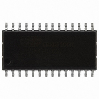
CS8420-CSZ Cirrus Logic Inc, CS8420-CSZ Datasheet - Page 46

CS8420-CSZ
Manufacturer Part Number
CS8420-CSZ
Description
IC SAMPLE RATE CONVERTER 28SOIC
Manufacturer
Cirrus Logic Inc
Type
Sample Rate Converterr
Specifications of CS8420-CSZ
Package / Case
28-SOIC
Applications
CD-R, DAT, DVD, MD, VTR
Mounting Type
Surface Mount
Operating Supply Voltage
5 V
Operating Temperature Range
- 10 C to + 70 C
Mounting Style
SMD/SMT
Resolution
17 bit to 24 bit
Control Interface
3 Wire, Serial
Supply Voltage Range
4.75V To 5.25V
Audio Ic Case Style
SOIC
No. Of Pins
28
Bandwidth
20kHz
Rohs Compliant
Yes
Audio Control Type
Volume
Dc
0841
Lead Free Status / RoHS Status
Lead free / RoHS Compliant
For Use With
598-1782 - EVALUATION BOARD FOR CS8420
Lead Free Status / Rohs Status
Lead free / RoHS Compliant
Other names
598-1125-5
Available stocks
Company
Part Number
Manufacturer
Quantity
Price
Company:
Part Number:
CS8420-CSZ
Manufacturer:
CIRRUS
Quantity:
319
Company:
Part Number:
CS8420-CSZ
Manufacturer:
CIRRUS
Quantity:
9 908
Part Number:
CS8420-CSZ
Manufacturer:
CIRRUS
Quantity:
20 000
Company:
Part Number:
CS8420-CSZ/D1
Manufacturer:
CIRRUS
Quantity:
378
Company:
Part Number:
CS8420-CSZR
Manufacturer:
NICHICON
Quantity:
4 200
46
10.18 User Data Buffer Control (13h)
UD
UBM[1:0]
DETUI
EFTUI
Q-Channel Subcode Bytes 0 to 9 (14h - 1Dh) (Read Only)
The following 10 registers contain the decoded Q-channel subcode data
ABS SECOND ABS SECOND ABS SECOND ABS SECOND ABS SECOND ABS SECOND ABS SECOND ABS SECOND
ABS MINUTE ABS MINUTE ABS MINUTE ABS MINUTE ABS MINUTE ABS MINUTE ABS MINUTE ABS MINUTE
ABS FRAME
CONTROL
SECOND
MINUTE
FRAME
TRACK
INDEX
ZERO
7
0
7
Each byte is LSB first with respect to the 80 Q-subcode bits Q[79:0]. Thus bit 7 of address 14h is Q[0] while
bit 0 of address 14h is Q[7]. Similarly bit 0 of address 1Dh corresponds to Q[79].
ABS FRAME
CONTROL
SECOND
MINUTE
FRAME
TRACK
INDEX
ZERO
User data pin (U) direction specifier
0 - The U pin is an input. The U data is latched in on both rising and falling edges of
OLRCK. This setting also chooses the U pin as the source for transmitted
U data (default).
1 - The U pin is an output. The received U data is clocked out on both rising and falling edges
of ILRCK. This setting also chooses the U data buffer as the source of transmitted
U data.
Sets the operating mode of the AES3 U bit manager
00 - Transmit all zeros mode (default)
01 - Block mode
10 - Reserved
11 - IEC consumer mode B
0 - Allow U-data D to E buffer transfers (default)
1 - Inhibit U-data D to E buffer transfers
E to F U-data buffer transfer inhibit bit (valid in block mode only).
0 - Allow U-data E to F buffer transfers (default)
1 - Inhibit U-data E to F buffer transfer
D to E U-data buffer transfer inhibit bit (valid in block mode only).
6
0
6
ABS FRAME
CONTROL
SECOND
MINUTE
FRAME
TRACK
INDEX
ZERO
5
0
5
ABS FRAME
CONTROL
SECOND
MINUTE
FRAME
TRACK
INDEX
ZERO
UD
4
4
ABS FRAME
ADDRESS
SECOND
MINUTE
TRACK
FRAME
INDEX
UBM1
ZERO
3
3
ABS FRAME
ADDRESS
SECOND
MINUTE
FRAME
TRACK
INDEX
UBM0
ZERO
2
2
ABS FRAME
ADDRESS
SECOND
MINUTE
FRAME
TRACK
INDEX
DETUI
ZERO
1
1
ABS FRAME
ADDRESS
SECOND
CS8420
MINUTE
FRAME
TRACK
INDEX
EFTUI
ZERO
DS245F4
0
0


