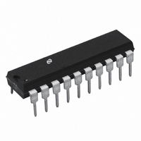
LM2202N National Semiconductor, LM2202N Datasheet - Page 2

LM2202N
Manufacturer Part Number
LM2202N
Description
IC VIDEO AMP SYSTEM 20-DIP
Manufacturer
National Semiconductor
Datasheet
1.LM2202M.pdf
(17 pages)
Specifications of LM2202N
Applications
General Purpose
Number Of Circuits
1
-3db Bandwidth
230MHz
Current - Supply
48mA
Current - Output / Channel
28mA
Voltage - Supply, Single/dual (±)
8 V ~ 13.2 V
Mounting Type
Through Hole
Package / Case
20-DIP (0.300", 7.62mm)
Lead Free Status / RoHS Status
Contains lead / RoHS non-compliant
Other names
*LM2202N
Available stocks
Company
Part Number
Manufacturer
Quantity
Price
Part Number:
LM2202N
Manufacturer:
NS/国半
Quantity:
20 000
www.national.com
I
V
V
V
I
I
I
I
V
V
V
R
A
THD
f
t
t
S
14L
14H
12+
12−
−3 dB
r
f
See Test Circuit ( Figure 1 ), T
wise noted.
Symbol
See Test Circuit ( Figure 1 ), T
erwise noted.
Symbol
6
14L
14H
17L
17H
OS
V
A
A
IN
DC Electrical Characteristics
AC Electrical Characteristics
Note 1: Absolute Maximum Ratings indicate limits beyond which damage to the device may occur.
Note 2: Operating Ratings indicate conditions for which the device is functional but do not guarantee specific performance limits. For guaranteed specifications and
test conditions see the Electrical Characteristics. The guaranteed specifications apply only for the test conditions listed. Some performance characteristics may de-
grade when the device is not operated under the listed test conditions.
Note 3: Typical specifications are specified at +25˚C and represent the most likely parametric norm.
Note 4: Tested limits are guaranteed to National’s AOQL (Average Outgoing Quality Level).
Note 5: The supply current specified is the quiescent current for V
pends on the output load, R
bient temperature.
Note 6: When measuring video amplifier bandwidth or pulse rise and fall times, a double sided full ground plane printed circuit board is recommended. The measured
rise and fall times are effective rise and fall times, taking into account the rise and fall times of the generator and the oscilloscope.
Absolute Maximum Ratings
If Military/Aerospace specified devices are required,
please contact the National Semiconductor Sales Office/
Distributors for availability and specifications.
Supply Voltage V
Voltage at Any Input Pin (V
Video Output Current (I
Package Power Dissipation at
Drive
4, 7, 16
V
V
max
Ground Pins 5, 13, 15
T
(Above 25˚C Derate Based
2V
0.5V
A
= 25˚C
Total Supply Current
Video Input Bias Voltage
Clamp Gate Low Input Voltage
Clamp Gate High Input Voltage
Clamp Gate Low Input Current
Clamp Gate High Input Current
Clamp Cap Charge Current
Clamp Cap Discharge Current
Video Output Low Voltage
Video Output High Voltage
Comparator Input Offset Voltage
Video Amplifier Input Resistance
Video Amplifier Gain
Attenuation at 2V
Attentuation at 0.5V
Video Amplifier Distortion
Video Amplifier Bandwidth (Note 6)
Output Rise Time (Note 6)
Output Fall Time (Note 6)
Gain Range
CC
Pins 4, 7, 16 to
Load
17
. The increase in device power dissipation due to R
)
Parameter
Parameter
IN
A
A
)
= 25˚C, V4 = V7 = V16 = 12V, S1 Open, V19 = 4V, V8 = 4V, V9 = 4V, V14 = 0V unless other-
= 25˚C, V4 = V7 = V16 = 12V, S1 Closed, V19 = 4V, V8 = 4V, V9 = 4V, V14 = 0V unless oth-
JA
and T
J
)
V
CC
(Note 1)
V
IN
CC1
28 mA
1.56W
13.5V
, V
GND
R
Clamp Comparator On
Clamp Comparator Off
V
V
V
V
V
V
V
f
V
Ref: A
Ref: A
V
V
V
V
V
IN
CC2
LOAD
14
14
12
12
12
12
18
8
9
O
O
O
O
= 12 kHz
= 4V, V
= 0V to 4V
= 4 V
= 4 V
= 4 V
= 4 V
− V
= 0V
= 12V
= 0V
= 5V
= 0V
= 6V
and V
V
V
=
2
19
Conditions
Conditions
max, V
max, V
Load
PP
PP
PP
PP
CC3
9
Junction Temperature (T
Storage Temperature Range (T
Lead Temperature
ESD Susceptibility
Operating Ratings
Temperature Range
Supply Voltage (V
, f
Package Thermal Resistance (
(Note 5)
with R
must be taken into account when operating the device at the maximum am-
= 4V
IN
N20A
M20B
N Package (Soldering, 10 sec.)
Human Body Model: 100 pF
Discharged through a 1.5k
Resistor
8
8
= 12 kHz
= 2V
= 0.5V
Load
=
, see Figure 1’s test circuit. The total supply current also de-
CC
)
(Note 3)
(Note 3)
Typical
Typical
0.005
−800
−0.5
−38
800
230
2.4
0.2
0.5
1.5
1.5
48
10
15
20
20
−6
J
6
)
stg
(Note 2)
JA
)
)
Limit (Note
Limit (Note
−500
0.65
500
±
−23
0.8
60
16
4)
4)
2
2
2
2
9
5
1
50
8V
−65˚C to +150˚C
−20˚C to +80˚C
V
CC
mA (max)
mV (max)
V/V (min)
µA (min)
µA (min)
dB (min)
dB (min)
ns (max)
ns (max)
% (max)
V (max)
V (max)
68˚C/W
90˚C/W
V (min)
V (min)
V (min)
Units
Units
1.5 kV
150˚C
265˚C
MHz
13.2V
µA
µA
k
dB


