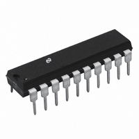
LM2202N National Semiconductor, LM2202N Datasheet - Page 12

LM2202N
Manufacturer Part Number
LM2202N
Description
IC VIDEO AMP SYSTEM 20-DIP
Manufacturer
National Semiconductor
Datasheet
1.LM2202M.pdf
(17 pages)
Specifications of LM2202N
Applications
General Purpose
Number Of Circuits
1
-3db Bandwidth
230MHz
Current - Supply
48mA
Current - Output / Channel
28mA
Voltage - Supply, Single/dual (±)
8 V ~ 13.2 V
Mounting Type
Through Hole
Package / Case
20-DIP (0.300", 7.62mm)
Lead Free Status / RoHS Status
Contains lead / RoHS non-compliant
Other names
*LM2202N
Available stocks
Company
Part Number
Manufacturer
Quantity
Price
Part Number:
LM2202N
Manufacturer:
NS/国半
Quantity:
20 000
www.national.com
Circuit Description
Applications
SINGLE VIDEO CHANNEL
A typical application for a single video channel is shown in
Figure 9 . The video signal is AC coupled to pin 6. The
LM2202 internally biases the video signal to 2.6 V
trast control is achieved by applying a 0V to 4V DC voltage
at pin 8. The amplifier’s gain is minimum (i.e., maximum sig-
nal attenuation) if pin 8 is at 0V and is maximum if pin 8 is at
4V. With pin 9 (drive control) at 0V, the amplifier has a maxi-
mum gain of 10.
For DC restoration, a clamp signal must be applied to the
clamp gate input (pin 14). The clamp signal should be logic
low (less than 0.8V) only during the back porch (black level
reference period) interval (see Figure 2 ). The clamp gate in-
put is TTL compatible. Brightness control is provided by ap-
plying a 0V to 4V DC voltage at pin 19. For example, if pin 19
is biased at 1V then the video signal’s black level will be
clamped at 1V. A 510
video output pin (pin 17) to ground. This resistor biases the
output stage of the amplifier. For power dissipation consider-
ations, the load resistor should not be much less than 510 .
FIGURE 8. Simplified Schematic of the LM2202 Clamp Comparator Circuit
load resistor is connected from the
(Continued)
DC
. Con-
12
RGB VIDEO PREAMPLIFIER
Figure 10 shows an RGB video preamplifier circuit using
three LM2202s. Note that pins 1 and 2 of IC1 are connected
to pins 1 and 2 of IC2 and IC3 respectively. This allows IC1
to provide a master contrast control and optimum contrast
tracking. Adjusting the contrast voltage at pin 8 of IC1 will
vary the gain of all three video channels. Drive control input
(pin 9) of each LM2202 allows individual gain adjustment for
achieving white balance.
The black level of each video channel can be individually ad-
justed to the desired voltage by adjusting the voltage at pin
19. In a DC-coupled cathode drive application, adjusting the
voltage at pin 19 of each IC will provide cutoff adjustment. In
an AC-coupled cathode drive application, the video signal is
AC coupled and DC restored at the cathode. In such an ap-
plication, the video signal’s black level may be clamped to
the desired level by simply biasing pin 19 to the black level
voltage by using a voltage divider at pin 19.
DS012591-14


