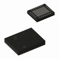
LM4804LQX/NOPB National Semiconductor, LM4804LQX/NOPB Datasheet - Page 9

LM4804LQX/NOPB
Manufacturer Part Number
LM4804LQX/NOPB
Description
IC AMP AUDIO PWR 1.9W MONO 28LLP
Manufacturer
National Semiconductor
Series
Boomer®r
Type
Class ABr
Datasheet
1.LM4804LQNOPB.pdf
(17 pages)
Specifications of LM4804LQX/NOPB
Output Type
1-Channel (Mono)
Max Output Power X Channels @ Load
1.9W x 1 @ 8 Ohm
Voltage - Supply
2.7 V ~ 6.1 V
Features
Depop, Short-Circuit and Thermal Protection, Shutdown
Mounting Type
Surface Mount
Package / Case
28-LLP
Operational Class
Class-AB
Audio Amplifier Output Configuration
1-Channel Mono
Output Power (typ)
1.9x1@8OhmW
Audio Amplifier Function
Speaker
Total Harmonic Distortion
0.13@8Ohm@1.5W%
Single Supply Voltage (typ)
Not RequiredV
Dual Supply Voltage (typ)
3/5V
Power Supply Requirement
Dual
Power Dissipation
1.8W
Rail/rail I/o Type
No
Power Supply Rejection Ratio
72dB
Single Supply Voltage (min)
Not RequiredV
Single Supply Voltage (max)
Not RequiredV
Dual Supply Voltage (min)
2.7/3V
Dual Supply Voltage (max)
5/6.1V
Operating Temp Range
-40C to 85C
Operating Temperature Classification
Industrial
Mounting
Surface Mount
Pin Count
28
Package Type
LLP EP
Lead Free Status / RoHS Status
Lead free / RoHS Compliant
Application Information
EXTERNAL COMPONENT SELECTION
Proper selection of external components in applications us-
ing integrated power amplifiers, and switching DC-DC con-
verters, is critical to optimize device and system perfor-
mance. Consideration to component values must be used to
maximize overall system quality.
The best capacitors for use with the switching converter
portion of the LM4804 are multi-layer ceramic capacitors.
They have the lowest ESR (equivalent series resistance)
and highest resonance frequency which makes them opti-
mum for use with high frequency switching converters.
When selecting a ceramic capacitor, only X5R and X7R
dielectric types should be used. Other types such as Z5U
and Y5F have such severe loss of capacitance due to effects
of temperature variation and applied voltage, they may pro-
vide as little as 20% of rated capacitance in many typical
applications. Always consult capacitor manufacturer’s data
curves before selecting a capacitor. High-quality ceramic
capacitors can be obtained from Taiyo-Yuden, AVX, and
Murata.
POWER SUPPLY BYPASSING
As with any amplifier, proper supply bypassing is critical for
low noise performance and high power supply rejection. The
capacitor location on both the bypass and power supply pins
should be as close to the device as possible.
SELECTING THE AUDIO AMPLIFIER’S INPUT
CAPACITOR
One of the major considerations is the closedloop bandwidth
of the amplifier. To a large extent, the bandwidth is dictated
by the choice of external components shown in Figure 1. The
input coupling capacitor, C
which limits low frequency response. This value should be
chosen based on needed frequency response for a few
distinct reasons.
Large input capacitors are both expensive and space hungry
for portable designs. Clearly, a certain sized capacitor is
needed to couple in low frequencies without severe attenu-
ation. But ceramic speakers used in portable systems,
whether internal or external, have little ability to reproduce
signals below 100Hz to 150Hz. Thus, using a large input
capacitor may not increase actual system performance.
i
, forms a first order high pass filter
(Continued)
9
In addition to system cost and size, click and pop perfor-
mance is effected by the size of the input coupling capacitor,
C
reach its quiescent DC voltage (nominally 1/2 V
charge comes from the output via the feedback and is apt to
create pops upon device enable. Thus, by minimizing the
capacitor size based on necessary low frequency response,
turn-on pops can be minimized.
SELECTING THE AUDIO AMPLIFIER’S BYPASS
CAPACITOR
Besides minimizing the input capacitor size, careful consid-
eration should be paid to the bypass capacitor value. Bypass
capacitor, C
turn-on pops since it determines how fast the amplifer turns
on. The slower the amplifier’s outputs ramp to their quies-
cent DC voltage (nominally 1/2 V
pop. Choosing C
C
virtually clickless and popless shutdown function. While the
device will function properly, (no oscillations or motorboat-
ing), with C
susceptible to turn-on clicks and pops. Thus, a value of C
equal to 1.0µF is recommended in all but the most cost
sensitive designs.
OPERATING PRINCIPLE
The LM4804 includes step-up DC-DC voltage regulation for
battery-powered and low-input voltage systems. It combines
a step-up switching regulator, N-channel power MOSFET,
built-in current limit, thermal limit, and voltage reference. The
switching DC-DC regulator boosts an input voltage between
.8V and 14V to a regulated output voltage between 1.24V
and 14V. The LM4804 starts from a low 1.1V input and
remains operational down to below .8V.
This device is optimized for use in cellular phones and other
applications requiring a small size, low profile, as well as low
quiescent current for maximum battery life during stand-by
and shutdown.
Additional features include a built-in peak switch current
limit, a high-efficiency gated-oscillator topology that offers an
output of up to 2A at low output voltages, and thermal
protection circuitry.
i
i
. A larger input coupling capacitor requires more charge to
(in the range of 0.039µF to 0.39µF), should produce a
B
B
, is the most critical component to minimize
equal to 0.1µF, the device will be much more
B
equal to 1.0µF along with a small value of
DD
), the smaller the turn-on
www.national.com
DD
). This
B


