LM4846TL/NOPB National Semiconductor, LM4846TL/NOPB Datasheet - Page 24
LM4846TL/NOPB
Manufacturer Part Number
LM4846TL/NOPB
Description
IC AMP AUDIO PWR 1.15W AB 25USMD
Manufacturer
National Semiconductor
Series
Boomer®r
Type
Class ABr
Datasheet
1.LM4846TLNOPB.pdf
(30 pages)
Specifications of LM4846TL/NOPB
Output Type
1-Channel (Mono) with Stereo Headphones
Max Output Power X Channels @ Load
1.15W x 1 @ 8 Ohm; 75mW x 2 @ 32 Ohm
Voltage - Supply
2.7 V ~ 5.5 V
Features
3D, Depop, I²C, Mute, Shutdown, SPI, Thermal Protection, Volume Control
Mounting Type
Surface Mount
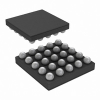
Package / Case
25-MicroSMD
Operational Class
Class-AB
Audio Amplifier Function
Headphone/Speaker
Total Harmonic Distortion
0.5@8Ohm@500mW%
Single Supply Voltage (typ)
3/5V
Dual Supply Voltage (typ)
Not RequiredV
Supply Current (max)
11@3.3VmA
Power Supply Requirement
Single
Rail/rail I/o Type
No
Power Supply Rejection Ratio
88dB
Single Supply Voltage (min)
2.7V
Single Supply Voltage (max)
5.5V
Dual Supply Voltage (min)
Not RequiredV
Dual Supply Voltage (max)
Not RequiredV
Operating Temp Range
-40C to 85C
Operating Temperature Classification
Industrial
Mounting
Surface Mount
Pin Count
25
Package Type
uSMD
For Use With
LM4846TLEVAL - BOARD EVALUATION LM4846TL
Lead Free Status / RoHS Status
Lead free / RoHS Compliant
Other names
LM4846TLTR


www.national.com
Application Information
NATIONAL 3D ENHANCEMENT
The LM4846 features a stereo headphone, 3D audio en-
hancement effect that widens the perceived soundstage
from a stereo audio signal. The 3D audio enhancement
creates a perceived spatial effect optimized for stereo head-
phone listening. The LM4846 can be programmed for a
“narrow” or “wide” soundstage perception. The narrow
soundstage has a more focused approaching sound direc-
tion, while the wide soundstage has a spatial, theater-like
effect. Within each of these two modes, four discrete levels
of 3D effect that can be programmed: low, medium, high,
and maximum (Table 2), each level with an ever increasing
aural effect, respectively. The difference between each level
is 3dB.
The external capacitors, shown in Figure 6, are required to
enable the 3D effect. The value of the capacitors set the
cutoff frequency of the 3D effect, as shown by Equations 1
and 2. Note that the internal 20kΩ resistor is nominal
(
PCB LAYOUT AND SUPPLY REGULATION
CONSIDERATIONS FOR DRIVING 8Ω LOAD
Power dissipated by a load is a function of the voltage swing
across the load and the load’s impedance. As load imped-
ance decreases, load dissipation becomes increasingly de-
pendent on the interconnect (PCB trace and wire) resistance
between the amplifier output pins and the load’s connec-
tions. Residual trace resistance causes a voltage drop,
which results in power dissipated in the trace and not in the
load as desired. For example, 0.1Ω trace resistance reduces
±
25%).
(optional)
R
3D
10
20
FIGURE 6. External 3D Effect Capacitors
0
1
5
(kΩ)
f
3DL(-3dB)
C
= 1 / 2π * 20kΩ * C
3D
68
68
68
68
68
(nF)
(Continued)
3DL
0.05
0.25
0.50
1.00
M
0
TABLE 6. Pole Locations
20166895
(1)
∆AV (dB)
–0.4
–1.9
–3.5
–6.0
24
0
Optional resistors R
7) to affect the -3dB frequency and 3D magnitude.
∆AV (change in AC gain) = 1 / 1 + M, where M represents
some ratio of the nominal internal resistor, 20kΩ (see ex-
ample below).
the output power dissipated by an 8Ω load from 158.3mW to
156.4mW. The problem of decreased load dissipation is
exacerbated as load impedance decreases. Therefore, to
maintain the highest load dissipation and widest output volt-
age swing, PCB traces that connect the output pins to a load
must be as wide as possible.
Poor power supply regulation adversely affects maximum
output power. A poorly regulated supply’s output voltage
decreases with increasing load current. Reduced supply
voltage causes decreased headroom, output signal clipping,
FIGURE 7. External RC Network with Optional R
f
f
f-3dB (3D)
3DR(-3dB)
3DL(-3dB)
f
3dB
(Hz)
117
111
94
78
59
f
3DR(-3dB)
C
(3D) = 1 / 2π (1 + M)(20kΩ * C
Equivalent
= 1 / 2π * (20kΩ + R
= 1 / 2π * 20kΩ + R
and R
3DL
= 1 / 2π * 20kΩ * C
and R
(new) = C
to keep same
3DR
Value of C
pole location
3DR
Resistors
64.8
54.4
45.3
34.0
(nF)
can also be added (Figure
3D
3D
/ 1 + M
3DR
3DL
) * C
) * C
3DR
new Pole
3D
Location
3DR
3DL
(Hz)
)
117
117
117
117
3DL
20166894
(2)
(3)
(4)
(5)
(6)
Related parts for LM4846TL/NOPB
Image
Part Number
Description
Manufacturer
Datasheet
Request
R

Part Number:
Description:
National Semiconductor [8-Bit D/A Converter]
Manufacturer:
National Semiconductor
Datasheet:
Part Number:
Description:
National Semiconductor [Media Coprocessor]
Manufacturer:
National Semiconductor
Datasheet:
Part Number:
Description:
Digitally Controlled Tone and Volume Circuit with Stereo Audio Power Amplifier, Microphone Preamp Stage and National 3D Sound
Manufacturer:
National Semiconductor
Datasheet:
Part Number:
Description:
Digitally Controlled Tone and Volume Circuit with Stereo Audio Power Amplifier, Microphone Preamp Stage and National 3D Sound
Manufacturer:
National Semiconductor
Datasheet:
Part Number:
Description:
AC97 Rev 2 Codec with Sample Rate Conversion and National 3D Sound
Manufacturer:
National Semiconductor
Part Number:
Description:
Manufacturer:
National Semiconductor
Datasheet:
Part Number:
Description:
Manufacturer:
National Semiconductor
Datasheet:
Part Number:
Description:
General Purpose, Low Voltage, Low Power, Rail-to-Rail Output Operational Amplifiers
Manufacturer:
National Semiconductor
Datasheet:
Part Number:
Description:
8-bit 20 MSPS flash A/D converter.
Manufacturer:
National Semiconductor
Datasheet:
Part Number:
Description:
Low Noise Quad Operational Amplifier
Manufacturer:
National Semiconductor
Datasheet:
Part Number:
Description:
Quad Differential Line Receivers
Manufacturer:
National Semiconductor
Datasheet:
Part Number:
Description:
Quad High Speed Trapezoidal? Bus Transceiver
Manufacturer:
National Semiconductor
Datasheet:
Part Number:
Description:
Dual Line Receiver
Manufacturer:
National Semiconductor
Datasheet:
Part Number:
Description:
TTL to 10k ECL Level Translator with Latch
Manufacturer:
National Semiconductor
Datasheet: