53892-7 TE Connectivity, 53892-7 Datasheet - Page 2
53892-7
Manufacturer Part Number
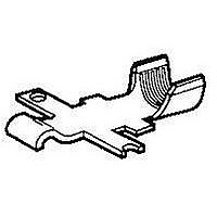
53892-7
Description
Power to the Board CONTACT CRIMP 18-12 Series 1
Manufacturer
TE Connectivity
Series
Series Ir
Specifications of 53892-7
Product Type
Contacts
Termination Style
Crimp
Contact Plating
Gold (30)
Contact Material
Copper
Wire Gauge Range
18-12
Wire Size (awg)
18-12
Termination Method To Wire/cable
Crimp
Ul File Number
E28476
Csa File Number
LR7189
Wire/cable Type
Discrete Wire
Make First / Break Last
No
Contact - Rated Current (a)
31
Operating Voltage Reference
AC
Operating Voltage (vac)
600
Wire/cable Size (awg)
12 – 18
Wire/cable Size (mm²)
0.811 – 3.09
Wire/cable Size (cma)
1,601 – 6,098
Profile Height (y-axis) (mm [in])
3.05 [0.120]
Length (x-axis) (mm [in])
18.29 [0.720]
Width (z-axis) (mm [in])
3.76 [0.148]
Underplate Material Thickness (µm [?in])
1.27 [50.000]
Contact Type
Pin/Socket
Contact Plating, Mating Area, Material
Gold
Contact Plating, Mating Area, Thickness (µm [?in])
0.762 [30]
Contact Base Material
Copper
Contact Design
Spring Latch
Underplate Material
Nickel
Rohs/elv Compliance
RoHS compliant, ELV compliant
Lead Free Solder Processes
Not relevant for lead free process
Rohs/elv Compliance History
Always was RoHS compliant
Vde Tested
No
Agency/standard
UL, CSA
Ul Rating
Recognized
Csa Certified
Yes
Operating Temperature (°c [°f])
-40 – +75 [-40 – +167]
Applies To
Wire/Cable
Accepts Wire Insulation Diameter, Range (mm [in])
0.864 – 0.914 [0.034 – 0.036]
Accepts Wire Material
Copper
Application Use
Wire-to-Wire
Contact Transmits (typical Application)
Power
Packaging Method
Loose Piece
Lead Free Status / Rohs Status
Details


3.4.
3.5.
Rev B
Exam ination of product.
Term ination resistance.
Insulation resistance.
Dielectric withstanding voltage.
Tem perature rise vs current.
Solderability.
Crim p tensile.
Vibration, sinusoidal.
Perform ance and Test Description
Product is designed to m eet electrical, m echanical and environm ental perform ance requirem ents
specified in Figure 1. Unless otherwise specified, all tests shall be perform ed at am bient environm ental
conditions per Test Specification 109-1.
Test Requirem ents and Procedures Sum m ary
Test Description
Meets requirem ents of product
drawing.
2.5 m illiohm s m axim um .
1000 m egohm s m inim um .
1500 vac at sea level.
30 C m axim um tem perature rise at
specified current of 31 am peres ac.
Solderable area shall have
m inim um of 95% solder coverage.
No discontinuities of 1
m icrosecond or longer duration.
See Note.
W ire Size
( AW G)
18
16
14
12
Figure 1 (continued)
MECHANICAL
ELECTRICAL
Requirem ent
(Lbs m axim um )
Crim p Tensile
20
30
50
50
TE 109-6-7.
TE Spec 109-28-4.
TE Spec 109-29-1.
Visual, dim ensional and functional
per applicable quality inspection
plan and Certificate of
Conform ance.
Subject m ated contacts assem bled
in housing to 50 m v m axim um open
circuit at 1 am pere m axim um .
See Figure 3.
Test between adjacent contacts of
m ated sam ples ganged together.
Test between adjacent contacts of
m ated sam ples ganged together
and a m etal plate.
See Figure 4.
TE Spec 109-45-1 and 109-151.
Measure tem perature rise vs
current.
See Figures 5 and 6.
TE Spec 109-11-2.
Subject contacts to solderability.
TE Spec 109-16.
Determ ine crim p tensile at
m axim um rate of 1 inch per m inute.
TE Spec 109-21-1.
Subject m ated sam ples to 10-55-10
Hz traversed in 1 m inute at .06 inch
total excursion. 1.3 hours in each of
3 m utually perpendicular planes.
See Figure 7.
Procedure
108-11026
2 of 9
Related parts for 53892-7
Image
Part Number
Description
Manufacturer
Datasheet
Request
R

Part Number:
Description:
CONTACT, 18-12AWG, CRIMP
Manufacturer:
TE Connectivity
Datasheet:

Part Number:
Description:
Power to the Board CONTACT PWR LK
Manufacturer:
TE Connectivity
Datasheet:
Part Number:
Description:
CONTACT,PWR LK,SRS1,STRIP,CRMP
Manufacturer:
TE Connectivity
Datasheet:

Part Number:
Description:
Printers THERMAL PRINTER HS-SLEEVE MARKER
Manufacturer:
TE Connectivity


Part Number:
Description:
High Speed / Modular Connectors 30P HEADER ASSY
Manufacturer:
TE Connectivity
Datasheet:

Part Number:
Description:
High Speed / Modular Connectors REC 6X005P R/A LT B-PLANE HS3
Manufacturer:
TE Connectivity
Datasheet:

Part Number:
Description:
High Speed / Modular Connectors 2MM HM RCPT 50P R/A AU
Manufacturer:
TE Connectivity
Datasheet:

Part Number:
Description:
High Speed / Modular Connectors 2MM HM RCPT 50P R/A AU
Manufacturer:
TE Connectivity
Datasheet:


Part Number:
Description:
Manufacturer:
TE Connectivity
Datasheet:


Part Number:
Description:
Manufacturer:
TE Connectivity
Datasheet:

Part Number:
Description:
Manufacturer:
TE Connectivity
Datasheet:

Part Number:
Description:
Manufacturer:
TE Connectivity
Datasheet: