1-2013496-1 TE Connectivity, 1-2013496-1 Datasheet - Page 4
1-2013496-1
Manufacturer Part Number
1-2013496-1
Description
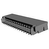
FFC / FPC Connectors 0.3MM 31POS FPC/FCC LCP HSG
Manufacturer
TE Connectivity
Specifications of 1-2013496-1
Product Type
PCB
Pitch
0.3 mm
Number Of Positions / Contacts
31
Mounting Angle
Right
Mounting Style
SMD/SMT
Actuation Type
ZIF
Contact Location
Bottom Contact
Termination Style
Solder Pin
Wire Type
FPC
Termination Method To Pc Board
Surface Mount
Pcb Mounting Orientation
Right Angle
Pcb Mount Alignment
Without
Pcb Mount Retention
With
Actuator Type
Rear Flip (Front Hinge)
Shrouded
Yes
Sealed
No
Strain Relief
Without
Contact Current Rating, Max (a)
0.2
Operating Voltage Reference
AC
Operating Voltage (vac)
50
Shielded
No
Tail Orientation
Staggered
Profile Height (y-axis) (mm [in])
1.20 [0.047]
Centerline (mm [in])
0.30 [0.012]
Number Of Positions
31
Selectively Loaded
No
Pcb Mount Retention Type
Solder Pads
Length (x-axis) (mm [in])
11.10 [0.437]
Width (z-axis) (mm [in])
2.90 [0.114]
Contact Plating, Mating Area, Material
Gold
Contact Plating, Mating Area, Thickness (µm [?in])
0.1 [3.937]
Tail Plating Material
Gold
Tail Plating, Thickness (µm [?in])
0.1 [3.93]
Contact Design
Single Beam
Housing Material
Liquid Crystal Polymer (LCP)
Contact Mating Location
Bottom
Flex Cable Thickness (mm [in])
0.2 [0.008]
Housing Color
Beige
Rohs/elv Compliance
RoHS compliant, ELV compliant
Lead Free Solder Processes
Reflow solder capable to 245°C
Rohs/elv Compliance History
Always was RoHS compliant
Circuit Identification Feature
Without
Operating Temperature (°c [°f])
-25 – +85 [-13 – +185]
Zif/non-zif
ZIF
Contact Transmits (typical Application)
Signal (Data)
Pick And Place Cover
Without
Packaging Method
Tape & Reel


3.5.6
3.5.6
3.5.7
3.5.7
3.5.8
3.5.8
3.5.9
3.5.9
3.5.10
3.5.10
Rev. C
Para.
項目
FPC保持力
FPC Retention Force
端子保持力
Contact Retention Force
耐久性
(繰り返し挿抜)
Durability
(Repeated Mating/
Un-mating)
振動
(低周波)
Vibration
(Low Frequency)
衝撃
Physical Shock
Test Items
試験項目
極数x0.2N 以上
POS. X 0.2N Min.
0.1 N 以上
0.1 N Min
総合抵抗 : 100mΩ以下 (終期) FPCを30回挿抜する。
Termination Resistance:
振動中1μsec.をこえる不連続
導通を生じないこと。
試験後、 物理的異常のなきこと。
総合抵抗 : 100mΩ以下 (終期)
外観に異常なきこと。
No electrical discontinuity
greater than 1μsec. shall
occur.
Termination Resistance:
No physical damage allowed.
衝撃により 1 μsec. をこえる
不連続導通を生じないこと。
試験後、 物理的異常のなきこと。
総合抵抗 : 100mΩ以下 (終期)
外観に異常なきこと。
No electrical discontinuity
greater than 1μsec. shall
occur.
Termination Resistance:
No physical damage allowed.
Product Specification
Fig. 1 (続く) Fig. 1 (CONT.)
Mechanical Requirements
規
Requirements
機 械 的 性 能
100mΩMax (Final)
100mΩMax (Final)
100mΩMax (Final)
格
値
FPCをコネクタに挿入し、アクチュエータ
ーを閉じた状態でFPCを引張る。
操作速度 : 25-100mm/min.
Extract FPC from connector with closed
actuator.
Operation Speed : 25-100mm/min.
コンタクト引抜力を軸方向に加えること。
操作速度 : 25±3mm/min.
Apply an axial pull-off load to contact.
Operation Speed : 25±3mm/min.
操作速度 : 25±3mm/min.
Mate and un-mate FPC for 30 cycles.
Operation Speed : 25±3mm/min.
嵌合したコネクタに1.52mmの振幅で、
10-55-10Hz に毎分1サイクルの割合で変化
する掃引振動を直交する三方向軸に2時間
ずつ与えること。DC 0.1Aを通電。
Subject mated connectors to 10-55-10 Hz
traversed in 1 minute at 1.52 mm
amplitude 2hours each of 3mutually
perpendicular planes.
d.c. 0.1A applied
加速度:490m/s
衝撃パルス波形:正弦半波
接続時間:11m/s
速度変化:X,Y,Z軸 正逆方向に各3回、
合計18回、JIS C 0041
Accelerated Velocity: 490m/S
Waveform: Sine half wave
Duration: 11ms
Velocity Charge: 3.4m/S
Number of Drops: 3drops each to normal
and reversed directions of X,Y,Z axes,
totally 18drops.
試
Procedures
2
。
験
108-78351
方
4 of 10
法
2
.
Related parts for 1-2013496-1
Image
Part Number
Description
Manufacturer
Datasheet
Request
R


Part Number:
Description:
CONNECTOR, SMT-IDC, 2 POS, 20 AWG
Manufacturer:
TE Connectivity
Datasheet:

Part Number:
Description:
CONTACT, RECEPTACLE, 20-16AWG, CRIMP
Manufacturer:
TE Connectivity
Datasheet:
Part Number:
Description:
CONTACT, RECEPTACLE, 20-16AWG, CRIMP
Manufacturer:
TE Connectivity
Datasheet:

Part Number:
Description:
Headers & Wire Housings RECPT 24-20 AWG 30 AU
Manufacturer:
TE Connectivity
Datasheet:

Part Number:
Description:
Manufacturer:
TE Connectivity
Datasheet:

Part Number:
Description:
Manufacturer:
TE Connectivity
Datasheet:

Part Number:
Description:
Manufacturer:
TE Connectivity
Datasheet:

Part Number:
Description:
Manufacturer:
TE Connectivity
Datasheet:

Part Number:
Description:
CONNECTOR, SMT-IDC PASS THRU, 2 POS, 20
Manufacturer:
TE Connectivity
Datasheet:

Part Number:
Description:
Conn D-Subminiature PL 9 POS 2.74mm Solder RA Thru-Hole 9 Terminal 1 Port
Manufacturer:
TE Connectivity
Datasheet:

Part Number:
Description:
Conn D-Subminiature RCP 9 POS 2.74mm Solder RA Thru-Hole 9 Terminal 1 Port
Manufacturer:
TE Connectivity
Datasheet:

Part Number:
Description:
Conn D-Subminiature RCP 9 POS 2.77mm Solder ST Thru-Hole 9 Terminal 1 Port Tray
Manufacturer:
TE Connectivity
Datasheet:

Part Number:
Description:
FFC/FPC CONNECTOR, RECEPTACLE 12POS 1ROW
Manufacturer:
TE Connectivity
Datasheet:

Part Number:
Description:
Manufacturer:
TE Connectivity
Datasheet: