1-2013496-1 TE Connectivity, 1-2013496-1 Datasheet - Page 3
1-2013496-1
Manufacturer Part Number
1-2013496-1
Description
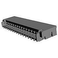
FFC / FPC Connectors 0.3MM 31POS FPC/FCC LCP HSG
Manufacturer
TE Connectivity
Specifications of 1-2013496-1
Product Type
PCB
Pitch
0.3 mm
Number Of Positions / Contacts
31
Mounting Angle
Right
Mounting Style
SMD/SMT
Actuation Type
ZIF
Contact Location
Bottom Contact
Termination Style
Solder Pin
Wire Type
FPC
Termination Method To Pc Board
Surface Mount
Pcb Mounting Orientation
Right Angle
Pcb Mount Alignment
Without
Pcb Mount Retention
With
Actuator Type
Rear Flip (Front Hinge)
Shrouded
Yes
Sealed
No
Strain Relief
Without
Contact Current Rating, Max (a)
0.2
Operating Voltage Reference
AC
Operating Voltage (vac)
50
Shielded
No
Tail Orientation
Staggered
Profile Height (y-axis) (mm [in])
1.20 [0.047]
Centerline (mm [in])
0.30 [0.012]
Number Of Positions
31
Selectively Loaded
No
Pcb Mount Retention Type
Solder Pads
Length (x-axis) (mm [in])
11.10 [0.437]
Width (z-axis) (mm [in])
2.90 [0.114]
Contact Plating, Mating Area, Material
Gold
Contact Plating, Mating Area, Thickness (µm [?in])
0.1 [3.937]
Tail Plating Material
Gold
Tail Plating, Thickness (µm [?in])
0.1 [3.93]
Contact Design
Single Beam
Housing Material
Liquid Crystal Polymer (LCP)
Contact Mating Location
Bottom
Flex Cable Thickness (mm [in])
0.2 [0.008]
Housing Color
Beige
Rohs/elv Compliance
RoHS compliant, ELV compliant
Lead Free Solder Processes
Reflow solder capable to 245°C
Rohs/elv Compliance History
Always was RoHS compliant
Circuit Identification Feature
Without
Operating Temperature (°c [°f])
-25 – +85 [-13 – +185]
Zif/non-zif
ZIF
Contact Transmits (typical Application)
Signal (Data)
Pick And Place Cover
Without
Packaging Method
Tape & Reel


3.5 性能必要条件と試験方法の要約
3.5 Test Requirements and Procedures Summary
3.5.1
3.5.1
3.5.2
3.5.2
3.5.3
3.5.3
3.5.4
3.5.4
3.5.5
3.5.5
Rev. C
Para.
項目
製品の確認
Examination of Product
総合抵抗
(ローレベル)
Termination Resistance
(Low Level)
耐電圧
Dielectric withstanding
Voltage
絶縁抵抗
Insulation Resistance
温度上昇
Temperature Rising
Test Items
試験項目
製品図面の必要条件に合致して
いること
Meets requirements of product
drawing.
沿面放電、フラッシュオーバー
等がないこと。
No creeping discharge nor
flashover shall occur.
定格電流を通電して、温度上昇
は 30℃ 以下
30℃ Max. under loaded
specified current.
Product Specification
50 mΩ 以下 (初期)
50 mΩ Max (Initial)
50 MΩ 以上 (初期)
50 MΩ Min (Initial)
Fig.1 (続く) Fig.1 (CONT.)
Electrical Requirements
規
Requirements
電 気 的 性 能
格
値
目視により、コネクタの機能上支障をきた
す損傷を検査する。
Visual inspection
No physical damage
FPCと嵌合したコネクタを開路電圧 20 mV
以下、閉路電流 100 mA 以下の条件で測定
する。
Fig. 1 参照。
Subject mated connector with FPC to 20
mV Max open circuit at 100 mA.
Fig. 1
200VAC, 1分間印加
FPC嵌合なし
プリント基板は取り付けない。
感度電流 : 2mA
200VAC for 1 minute.
Test between adjacent circuits of
unmated connector.
Trip Current : 2mA
100V DC, 1分間印加
FPC嵌合なし
プリント基板は取り付けない。
EIA-364-21C
Impressed voltage 100 V DC for 1 minute.
Test between adjacent circuits of
unmated connector.
EIA-364-21C
通電による温度上昇を測定すること。
(タイン部を測定)
EIA-364-70A
Measure temperature rising by energized
current.
(Measurement of tine)
EIA-364-70A
試
Procedures
験
108-78351
方
3 of 10
法
Related parts for 1-2013496-1
Image
Part Number
Description
Manufacturer
Datasheet
Request
R


Part Number:
Description:
CONNECTOR, SMT-IDC, 2 POS, 20 AWG
Manufacturer:
TE Connectivity
Datasheet:

Part Number:
Description:
CONTACT, RECEPTACLE, 20-16AWG, CRIMP
Manufacturer:
TE Connectivity
Datasheet:
Part Number:
Description:
CONTACT, RECEPTACLE, 20-16AWG, CRIMP
Manufacturer:
TE Connectivity
Datasheet:

Part Number:
Description:
Headers & Wire Housings RECPT 24-20 AWG 30 AU
Manufacturer:
TE Connectivity
Datasheet:

Part Number:
Description:
Manufacturer:
TE Connectivity
Datasheet:

Part Number:
Description:
Manufacturer:
TE Connectivity
Datasheet:

Part Number:
Description:
Manufacturer:
TE Connectivity
Datasheet:

Part Number:
Description:
Manufacturer:
TE Connectivity
Datasheet:

Part Number:
Description:
CONNECTOR, SMT-IDC PASS THRU, 2 POS, 20
Manufacturer:
TE Connectivity
Datasheet:

Part Number:
Description:
Conn D-Subminiature PL 9 POS 2.74mm Solder RA Thru-Hole 9 Terminal 1 Port
Manufacturer:
TE Connectivity
Datasheet:

Part Number:
Description:
Conn D-Subminiature RCP 9 POS 2.74mm Solder RA Thru-Hole 9 Terminal 1 Port
Manufacturer:
TE Connectivity
Datasheet:

Part Number:
Description:
Conn D-Subminiature RCP 9 POS 2.77mm Solder ST Thru-Hole 9 Terminal 1 Port Tray
Manufacturer:
TE Connectivity
Datasheet:

Part Number:
Description:
FFC/FPC CONNECTOR, RECEPTACLE 12POS 1ROW
Manufacturer:
TE Connectivity
Datasheet:

Part Number:
Description:
Manufacturer:
TE Connectivity
Datasheet: